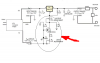
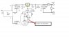
Correct, but you would remove R3 also. Take a look at the link that I gave..that should help. You will also remove the -5v that is shown in the diagram and use ground instead.
For the current, you don't have to worry about it. Basically use can either have a voltage source (what this circuit is) or a current source. With a voltage source, you set the voltage and the current will adjust to what it needs to be based on the resistance between the electrodes (Ohm's Law). The only issue you could run into is if this current was more than the regulator could handle. The regulator can handle a few amps (depending on which one you are actually using). If the current you need is in the mA range, you will have no issues at all.
With a current source (not what this circuit is), you send a fixed current through the system and the voltage will change depending on the resistance. Current sources are good for some things, but voltage sources are usually a bit easier to work with.
Are you at a univeristy or perhaps a lab? In either case, I would think that you could find someone with basic electronics knowledge to help you out. I certainly don't mind helping, but there is only so much help that I can provide without being there to see how you actually built the circuit.
Yes, you will be limited to about 1.2-1.25v as a minimum voltage with this circuit. However, if you get this working, then you can add the parts that were removed and then you will be able to adjust all the way down to 0v. Circuits are often designed/drawn/tested in blocks. Each part of the circuit does one simple job. You can build/test each of these blocks and then combine them as the circuit becomes more complicated. So, there is nothing wrong with starting off simple (1.2v minimum circuit) and then adding in the other parts later to be able to get down to 0v once you know the simple version works.