Users who are viewing this thread

Pawpaw

New Member
Messages
19
Reaction score
1
Points
3
Location
Ohio
Hello all,

It seems I've been reading a lot on this forum lately, so many thanks already!

I'm trying to address a submersible well pump that is short-cycling (58sec on, 28sec off, @9-10.5GPM). I would like to solve the short-cycling in a manner that minimizes the long-term average operating costs of the well water system, without unreasonably risking it's reliability.

In the past, a cycle stop valve (CSV, Flomatic Cycle Gard C153[...]) was used to eliminate the short-cycling. However, one simply stopped doing its job, and the last was removed after it learned to howl loudly without warning. Subsequently, I learned more about the system, and I discovered that the options are not nearly as simple or cheap as I had hoped. Thus, I am here hoping that some expert eyes will double check my assessment before I move forward.

Usage:
The well water system supplies a household of 3, who (presumably) have normal water demands. The house is heated & cooled using an open-loop (aka pump & dump) geothermal unit supplied from the same well water system (geothermal return water is sent down a separate well). This geothermal unit will demand a variable flow of water, up to 10.5 GPM. The geothermal unit contains a variable speed compressor, and I believe will attempt to run as slow and as long as possible to maintain temperature. Thus, it could be drawing water for lots of time.

According to the well drilling report in 1993:
Borehole is 8-3/4"
Casing is 5-5/8" diameter, ~88' long, welded steel, with 0.144" wall
Well is 130' deep
Static water level is 21' below ground

Pump:
Goulds 10GS10412CL (https://goulds.com/submersible-well...-hp-standard-capacity/#product-tab-literature),
4” nominal diameter,
1 HP,
Single-phase, 230V, 3-wire,
Maximum head pressure: ~455’ H2O (page 5, B5-25GS-R8.pdf),
Recommended operating range: 3-16 GPM (page 5, B5-25GS-R8.pdf),
Recommended limit of starts per 24h: 100 (page 3, BMAID-R11.pdf)
Recommended minimum run time: 1 minute (page 3, BMAID-R11.pdf)
Minimum flow for motor cooling (0.25'/sec): 1.2 GPM in 4" well or sleeve, 7 GPM in 5", 13 GPM in 6" (page 4, BMAID-R11.pdf)
No flow sleeve is installed
Wired to a Franklin Electric QD control box (capacitor start, model 2801084915)
Located 105' below ground

Control & storage:
A standard pressure switch is used, 50/70 PSI
Pressure tank is 22 gal, with 46 PSI pre-charge, so ~5gal drawdown
The pressure switch and pressure tank are located in the basement, whose floor is 9' above the ground at the well

Plumbing:
Drop pipe: Unsure. Attached to the top of the last pump removed is a piece of 1" black polyethylene (PE) pipe, seemingly SIDR-11.5. I presume this is the current drop pipe.
Pitless adapter: Dicken 2-JR-S-10, ~4' below ground
Pipe entering the basement: 1-1/4" black PE, SIDR-7 (best I could tell)
Then to the pressure tank: some 1-1/4" black PE 3408 SIDR-15 pressure class (PC) 100 pipe, and a mix of copper, brass, & PVC

Additional notes:
The well was able to produce 24 GPM for 1/2-hour in 2018
I have checked the tank pre-charge & drawdown; the pressure tank seems to be operating correctly

I am aware of a number of strategies to solve this problem:
Abandon geothermal
Convert to closed-loop geothermal
Add a dedicated well for the open-loop geothermal
Change the pump
Put a second pump in the same well
Replace or add another pressure tank
Increase the pressure switch differential (if both the occupants and acceptance factor allow)
Install a variable frequency drive (VFD)
Install a CSV

Again, my goal is to stop the short-cycling in a way that minimizes the long-term average operating costs of the well water system, without unreasonably risking it's reliability. At first glance, I'd say the CSV strategy seems like the best fit. I am a bit wary because the causes of the prior CSV failures were not determined. Nonetheless, I continue to consider a CSV because the prior failures might have been caused by debris, incorrect installation position, a manufacturing defect, or a design issue, all of which are addressable. However, there is further concern: if a CSV is put in the basement, the worst case pressure that could be experienced is ~197 PSI (455' H2O) in submerged drop pipe, ~190 PSI (438' H2O) at the pitless adapter, ~184 PSI (425' H2O) in the basement plumbing prior to the CSV, and ~124 PSI across a 60 PSI CSV.

It seems as though the system may have withstood such pressure in the past, but I can't sign off on that. The PC 100 PE in the basement is greatly underrated, but fortunately it is easily replaced. The 1-1/4" SIDR-7 PE entering the basement may be adequately rated, but I don't know what else is between the basement wall and the 1" threads of the pitless adapter. The pitless adapter may be “tested to 150PSI”, but it is unclear whether this is or is in excess of the working pressure, or is just a quality control test. I also can't anticipate whether repeatedly pressurizing the pitless adapter to 190PSI would merely cause temporary, inconsequential seal leakage, or whether it may lead to seal failure or permanent damage. I suspect the drop pipe is not rated to handle ~197 PSI. Even if I have the drop pipe adequately upgraded, there still remains uncertainty about the pitless adapter and buried supply piping. Therefore, a CSV would have to go in the well.

My plan at this point is to get the drop pipe upgraded to PC 200, a 4" flow sleeve installed, and a CSV installed just below the pitless adapter. Associated unpleasantness include:
A) The upfront cost for this strategy now includes drop pipe replacement & a flow sleeve (the latter is probably necessary regardless).
B) I will have to use the same model CSV that has had trouble in the past, because it is the only arrangement I know of that can go in the casing & tolerate over 125 PSI differential.
C) It may not be heard if it starts wailing again.
D) It will now be impractical to either put a filter upstream of the CSV, or create some plumbing to backflush debris out of the CSV.
E) CSV issues will now necessitate calling a well service.
F) CSV cleaning/rebuilding is not an option in situ, and is now more headache/money ex situ.
G) It will not be possible to log pressure-flow correlation from the basement to determine dynamic pumping level, potentially supporting the selection of a smaller pump in the future.
H) It is unknown how well this pump reduces power when choked back (allegedly, Goulds pumps may be poor in this regard).

So, here are my questions:
1) Is my plan the only logical arrangement of a CSV in this system?
2) Is it unwise to use a CSV in this situation? Would installing a VFD (for the same 1-phase pump) be more consistent with my goal?

Thanks in advance.
 
Last edited:

VAWellDriller

Active Member
Messages
539
Reaction score
111
Points
43
Location
Richmond, VA
I like using CSV or similar mechanical valves, and keeping things simple. An option would be to switch to a lower head pump; I'll stick with Goulds brand since that's what you have.

Given the details provided, I doubt your well draws down very far.....a quick pump test to determine actual pumping water level may be very useful.

I would bet that a 10GS07 (3/4HP 10 GPM) would meet your needs just fine...(and save a lot of money over the long run...saving a couple amps on open loop geo system can really add up).

If the water level did drop closer to the pump setting, you could switch it out for a 13GS10 (13gpm 1HP).

Either of these pumps will result in a big drop in backpressure; so you could keep the CSV in a serviceable location.
 

Reach4

Well-Known Member
Messages
39,780
Reaction score
4,654
Points
113
Location
IL
My plan at this point is to get the drop pipe upgraded to PC 200
What is PC 200 pipe? I would think you would be running either 1-1/4 or 1 inch schedule 80 PVC drop pipe, or SIDR polyethylene pipe. Maybe you meant to type PE for polyethylene.
 

Valveman

Cary Austin
Staff member
Messages
15,104
Reaction score
1,429
Points
113
Location
Lubbock, Texas
Website
cyclestopvalves.com
In the past, a cycle stop valve (CSV, was used to eliminate the short-cycling. However, one simply stopped doing its job.

Well the CSV was apparently working. Which CSV did yo have? Why did it fail? They are simple mechanical valves and not prone to failure. It may have just had a chunk of rust holding it open? I would have made sure it was right, given the chance.

Like VA says there are pumps better suited to your well depth. The 10GS10 you have will pump from a max of 390', and your water is only 20' deep. However, 390' means that pump can only build 168 PSI. Subtract the 10 PSI from having to lift from the 21' static level, and the back pressure on the CSV and pitless can only be a max of 158 PSI. With the CSV set at 60 PSI that is only 98 PSI differential. All of those numbers are more than the CSV125 can handle, but well within the limits of the CSV1A. The CSV1A should last for decades with that kind of pressure. You had the best option working. Just need to figure out why it failed and your life will be much easier. One thing for sure, your pump will not survive cycling on for 58 seconds and off for 29 seconds for very long.

You have thought all this out so well and done your homework. You should start looking for a more efficient pump also as VA says. You can go down a 1/4HP which will cut the electric bill by 25% right off the bat. Then if you look for a pump that has a good drop in horsepower when restricted with the CSV, it could save another 25% on the electric bill. Look at the performance curve and horsepower curve for the 10S07-12 and the 16S10-10 Grundfos pumps. Either of these will reduce the back pressure on the CSV, pitless, and everything else. But more importantly they will use less electricity when pumping small flow rates of water.
 

Pawpaw

New Member
Messages
19
Reaction score
1
Points
3
Location
Ohio
By PC I meant pressure class. I'm sorry, I've now fixed where I should have had it's definition. I plan to continue with polyethylene drop pipe, unless there is a reason not to. So for example, Charter Plastics PE resin 4710 PC 200 pipe is SIDR-9 (1" has minimum wall of 0.117", https://www.charterplastics.com/pe-4710-idr). Perhaps it's too stiff and unwieldy to send down a casing?

The prior CSVs were Flomatic Cycle Gard C153[...]. I wish I knew what caused them to fail, but I doubt a diagnosis was even attempted (in all fairness, Flomatic does warn against opening them). Debris is certainly a strong candidate. There is no doubt that they prevented short-cycling before they failed, though I am surprised that certain plumbing seemingly tolerated all that back pressure.

I would certainly like to switch to a lower power, lower head pump if I can. I wasn't very involved when a well & pump company replaced the pump in 2018. The 10GS10 seems like a reasonable choice if the pumping level is expected to be 100' down (it would still supply ~13 GPM @ 50 PSI in the house). In light of that, and also because I lack dynamic pumping level info, perhaps I've become too accepting of their decision. Is a quick test for pumping level rather definitive? Would the pumping level (or even the static level for that matter) fluctuate by season and weather conditions? What flow would you test at?

As for the economic savings of a pump change, I roughly estimate that they are rather small. Please critique my approximations & late night math:

Approximations:
Geo operates 6 months per year (not much cooling is done)
30 days per month
Geo operates 8 hours per day (wild guess)
Current pump always consumes 1HP when running, regardless of flow
1 HP = 0.75 kW
Effective marginal electricity cost: $0.076/kWh (accurate)
Changing from a 1HP to a 3/4HP pump yields a 25% energy reduction

6 x 30 x 8 x 0.75 x 0.076 x 0.25 = $21/year

I've yet to get a quote on my plan. The CSV is ~$200. What are ballpark figures on the cost of materials and labor for adding 100' of 1" PE (SIDR-7) drop pipe, and a flow sleeve? What does a 10GS07 run, $1000?

valveman: Do I understand correctly that the CSVS125 is limited to 150 PSI upstream pressure (meaning the differential is 110/100/90 PSI)?
 
Last edited:

Valveman

Cary Austin
Staff member
Messages
15,104
Reaction score
1,429
Points
113
Location
Lubbock, Texas
Website
cyclestopvalves.com
The prior CSVs were Flomatic Cycle Gard C153[...]. I wish I knew what caused them to fail, but I doubt a diagnosis was even attempted (in all fairness, Flomatic does warn against opening them). Debris is certainly a strong candidate. There is no doubt that they prevented short-cycling before they failed, though I am surprised that certain plumbing seemingly tolerated all that back pressure.

THANK YOU! So, they were not Cycle Stop Valves or CSV's that failed, but rather Flomatic Cyclegard valves. While I am very flattered that Flomatic copies everything I do, I do not like getting a bad reputation from failed copies of a Cycle Stop Valve. I have been feeding my family off the good reputation of Cycle Stop Valves since 1993. I have a new granddaughter I am very proud of that I plan on helping to feed selling Cycle Stop Valves for another 30 years. Thank you for making it clear that is was not a Cycle Stop Valve that failed and caused you so much trouble.

Since my patents expired in 2013, there is no reason for someone making a copy of a Cycle Stop Valve to make a bad one. However, there have been lots of failures with that particular CycleGard valve as it is a hard model to get right. The biggest problem with Flomatic Cyclegard valves is the lack of support. It is very aggravating that my competitors customers are told to call me when they have a problem, as Flomatic has no one who knows how they work.

If you had called me, I would have done the math and said that model Cyclegard is a copy of the Cycle Stop Valve model CSV125, and they are not designed to handle more than 150 PSI back pressure. Although it was probably just a bad valve and your 159 PSI of back pressure was not the cause of failure, it is still above the max pressure limit, which is why I recommend a CSV1A instead. Even though the Cyclegard valves didn't last very long, as you said, "there is no doubt they prevented short-cycling until they failed". You just need a real Cycle Stop Valve model CSV1A that will last 20-30 years.

Although choosing a different pump could be more efficient and save some energy, there is nothing wrong with the 10GS10 pump you have. Adding a Cycle Stop Valve now won't do anything about the damage that has already been caused by the short cycling the pump has been through already. But the sooner you add a CSV1A the less damage your pump will have.

A long pumping test at high flow rate would give you the actual pumping level and you could make sure of the pump size needed. But without doing a draw down test on the well, using the 10GS10 pump you have will cover you if the pumping level drops to 100' or so.
 

Valveman

Cary Austin
Staff member
Messages
15,104
Reaction score
1,429
Points
113
Location
Lubbock, Texas
Website
cyclestopvalves.com
Just an FYI. When the Cyclegard C153 first came out they all failed. I made the mistake of showing one of their customers that the valve did not even have an air vent, which is why they would not work. That guy went straight to Flomatic and told them how to fix the problem. Flomatic recalled all those models and had a proper air vent installed, now they should work better. But again, that is a hard one to get right even with me telling them how to do it. Lol!
 

Reach4

Well-Known Member
Messages
39,780
Reaction score
4,654
Points
113
Location
IL
Current pump always consumes 1HP when running, regardless of flow
1 HP = 0.75 kW
Pump motor systems are around 60% efficient, so 1.5 KW might be closer, unless you have actually put a wattmeter on the supply to your pump, and I don't think you did.


Wired to a Franklin Electric QD control box (capacitor start, model 2801084915)

A CSR (adds run capacitor) Franklin 2824085015 would reduce power consumption some. You can also add a run capacitor across two pump wires using your current control box for the same effect.
 

Pawpaw

New Member
Messages
19
Reaction score
1
Points
3
Location
Ohio
So, they were not Cycle Stop Valves or CSV's that failed, but rather Flomatic Cyclegard valves. While I am very flattered that Flomatic copies everything I do, I do not like getting a bad reputation from failed copies of a Cycle Stop Valve.
I see the confusion, my apologies Valveman. I was aware of your company "Cycle Stop Valves" (obviously abbreviated CSV), and your products named "CSV...". Somehow, I concluded that "cycle stop valve" or "CSV" is also the accepted term for the class of products intended to maintain downstream pressure above a certain flow rate. What is the correct term?

that model Cyclegard is a copy of the Cycle Stop Valve model CSV125, and they are not designed to handle more than 150 PSI back pressure. Although it was probably just a bad valve and your 159 PSI of back pressure was not the cause of failure, it is still above the max pressure limit
You lost me with 159 PSI. My worst case numbers are higher:
CSV @ basement: 184 PSI back pressure before CSV, 124 PSI differential over 60 PSI CSV
CSV @ pitless: 190 PSI back pressure before CSV, 130 PSI differntial over 60 PSI CSV
However, the conclusion remains: these numbers all exceed the specs of your CSVS125, and from what you're saying, it sounds unwise to put a C153[...] in those conditions too. Thus, my plan to hang the pump from a CSV at the pitless adapter is sounding more questionable.

So here is the question (to all): does anyone make such a valve that tolerates the pressures of my present system, fits in the casing and can support the weight of the pump?

Pump motor systems are around 60% efficient, so 1.5 KW might be closer, unless you have actually put a wattmeter on the supply to your pump, and I don't think you did.
That's a good catch, and I have not measured with a power meter. On further examination, I see there is a service factor to contend with too. So without an actual power curve, how would I know whether my pressure-flow operating point is above or below the "full load" power?

A CSR (adds run capacitor) Franklin 2824085015 would reduce power consumption some. You can also add a run capacitor across two pump wires using your current control box for the same effect.
I'll look into the literature and see if I can get an estimated power saving on that too.
 
Last edited:

Reach4

Well-Known Member
Messages
39,780
Reaction score
4,654
Points
113
Location
IL

Attachments

  • img_5.png
    img_5.png
    85.9 KB · Views: 333

Valveman

Cary Austin
Staff member
Messages
15,104
Reaction score
1,429
Points
113
Location
Lubbock, Texas
Website
cyclestopvalves.com
Sorry for the delay. Was baby sitting and enjoying the Granddaughter this weekend. This is the first I heard that the valve needs to be installed in the well casing. That is a limiting factor. And I don't know where you are getting those numbers for back pressure? The curve for the 10GS10 shows a max head of 390', which is the same as 168 PSI. Being as the CSV would be about 8' down the well, we can't subtract the full 21' from static, only 13' to the CSV. 390' minus 13' equals 377', which is the same as 163 PSI. That is still more than the 150 PSI max we recommend for the CSVS125. However, we have made a few improvements that our competitors haven't figured out yet. :) Except for having slightly more than a 2 GPM minimum and possibly making slightly more noise, the CSVS125 would still work. and I would stand behind it.

Putting the CSVS125 in the well means the pitless and anything after the CSV will only see the 50 to 70 PSI from the pressure switch, not the back pressure from the CSV. However, the CSV1A is much better suited for those pressures if it is possible to put the CSV after the pitless adapter?

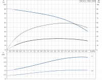
I would also recommend switching the 10GS10 pump end for the 16S10-10 Grundfos. You can use the same motor as long as it is not already compromised from all the cycling. As you can see from the attached curve it will still do 12 GPM at 240' of head, in case your water level pulls down to 100'. As you can also see it will only build 300' max, which is the same as 129 PSI max. Minus 5 PSI from the 13' static to the CSV and max pressure on the CSVS125 would only be 124 PSI.

Also, submersibles can have a service factor of 1.65. So, this 1HP can draw as much as 1.5HP at full flow. But when the CSV is restricting the flow to 2 GPM, the horsepower draw drops from 1.5HP all the way to 0.5HP. Add a CSCR control box to this setup and you will have a very efficient system that won't build more pressure than the CSVS125 can handle.


16S10-10 curve.png
 

Pawpaw

New Member
Messages
19
Reaction score
1
Points
3
Location
Ohio
Sorry for the delay. Was baby sitting and enjoying the Granddaughter this weekend.
That's perfectly OK; no apology needed.

What is the correct term?
I mean this. If using "CSV" to describe all these products with similar function is incorrect & tarnishes the reputation of yours, then please tell me the proper name and I'll happily use it.

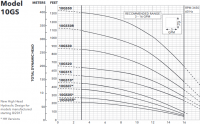
I don't know where you are getting those numbers for back pressure? The curve for the 10GS10 shows a max head of 390'
See the attached image. Source: Goulds website, technical brochure B5-25GS-R8.pdf, page 5.
I must assume I'm using this version, since my pump was installed 2018.

Putting the CSVS125 in the well means the pitless and anything after the CSV will only see the 50 to 70 PSI from the pressure switch, not the back pressure from the CSV. However, the CSV1A is much better suited for those pressures if it is possible to put the CSV after the pitless adapter?
Considering the pressures involved, that is precisely why I think the casing is the only place I can put a CSV, otherwise I'd love to put a CSV1A in the basement.
 

Attachments

  • Goulds_10GS_curves.png
    Goulds_10GS_curves.png
    103.7 KB · Views: 413

Valveman

Cary Austin
Staff member
Messages
15,104
Reaction score
1,429
Points
113
Location
Lubbock, Texas
Website
cyclestopvalves.com
Wow! Thanks for posting that curve. I am using a Goulds book from 2004-2005. I will now throw it away. I didn't know they made that change in 2017. You are very correct! That pump will build 194 PSI, which is more than the CSVS125 can handle, and maybe more than your pitless and/or underground pipe can handle. Sorry to confuse you! Being as you are in Ohio, your pitless will be too deep to install the CSV1A after the pitless and before the underground pipe. A valve box outside the well and a pitless that can take 190 PSI would be the only way to use the CSV1A.

I am back to swapping the pump end to a 16S10-10, which will be much more efficient anyway. This would let you install a CSVS125 in the well, where only the drop pipe below the CSVS125 would see up to 129 PSI. Or you could install a CSV1A at the pressure tank, and not have more than 124 PSI pressure your underground line and pitless.

Without having to pull and change the pump you could add a larger pressure tank and just reduce the number of cycles. Then you could put in a better pump that would work with a CSV when the time comes. Another option is to try one of the new single phase VFD's. In a short time you will know if these last any longer or work any better than the last 30 upgrades they have made to VFD's over the years. However, the larger pressure tank would be more efficient, as the pump is either running at its best efficiency point or it is off. With a VFD or a CSV, even though the amps are reduced considerably, the pump is no longer running at its best efficiency point and will cost more per gallon to pump. With a CSV any added cost per gallon in energy is usually cancelled out by the longevity of the pump and equipment. That hasn't generally been the case with VFD's.

As for the term "CSV"...
I started using that as an abbreviation for Cycle Stop Valves. The term "Cycle Stop Valves" is trademarked, CSV is not. It has sort of become the generic term my competitors use, even calling theirs a CSV Valve, which is technically a Cycle Stop Valve Valve. Lol! I am flattered and hope it sticks like Cresent Wrench. When I give classes and have to be generic, I use the term Constant Pressure Valve. Thank you so much for all the good details. I hope I was more help than I was trouble. :)
 

Pawpaw

New Member
Messages
19
Reaction score
1
Points
3
Location
Ohio
I hope I was more help than I was trouble. :)
No problem; I appreciate your help. At this point, question #1 and part of question #2 from my OP seem to be settled. You echoed my concern about excessive pressure at the pitless & beyond. You confirmed that it would be a bad idea to put the CSVS125 before the pitless.

On paper, the C153[...] should tolerate being before the pitless adapter. Yet what I've heard (admittedly from the competitor :)), together with all the unpleasantness of the arrangement listed in the OP, leaves me unwilling to try the C153[...] there. So, the CSV-before-pitless plan is now entirely dependent on one question: Is there any other CSV that'd fit in the casing and handle the pressures? If not, then I have to consider those other strategies.

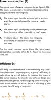
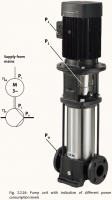
I am working to tighten up my energy approximation. I'm in the midst of tracking how long the geothermal runs. As for pump power, what "power" & "efficiency" is conventionally spoken about? Grundfos distinguishes between P_1, P_2 & P_H (see page 91 of their pump handbook https://api.grundfos.com/literature/Grundfosliterature-5448843.pdf):
P_1: "The power input from the mains or, put in another way, the amount of power the consumer has to pay for"
P_2: "The power input to the pump or the power output from the motor. Often referred to as shaft power"
P_H: "Hydraulic power – the power that the pump transfers to the liquid in the shape of flow and head"
There are a number of different efficiencies depending on which of the above are used.

The Grundfos 16S10-10 seems to have a rated P_2 power of 0.75kW (1HP), with a 1.4 service factor. The P_1 curve shown peaks at ~2.6kW (~3.5 HP)! That's certainly a surprise to me, but at least the data reveals it. What am I to assume about the total power (P_1) required for say a Grundfos 10S07-12, where only the P_2 is given, or a Goulds, where no power curve is given?

Regarding terminology, I will continue to use CSV generically then. I too suspect widespread use will probably be a net benefit for your company. Just be careful it doesn't jeopardize your trademark status.
 
Last edited:

LLigetfa

DIYer, not in the trades
Messages
7,548
Reaction score
607
Points
113
Location
NW Ontario, Canada
@valveman what about using two CSVs in series in the well, or one in the well and the other at the tank? You have prescribed that for others where the pressure was too high.
 

Valveman

Cary Austin
Staff member
Messages
15,104
Reaction score
1,429
Points
113
Location
Lubbock, Texas
Website
cyclestopvalves.com
The horsepower curve I showed for the 16S10-10 is the correct one. Below is the horsepower curve for the 10S07-12. I think other pump companies fo not show a horsepower curve because it isn't that good of a drop. If you can find the efficiency curves, which sometimes the factory will supply those, you can use our horsepower calculator to determine the power at low flow here. https://cyclestopvalves.com/pages/horse-power-calculator

The competitors C153 valve won't handle as much pressure as the original Cycle Stop Valve CSVS125.

The Cycle Stop Valves that fit in the well have a max output pressure of 60 PSI. Can't really split the difference in pressure with that. If we had a valve that fit in the well that could take the 190 PSI from the pump and regulate it to say 120 PSI, then another CSV1A after the pitless could take it from 120 to 60 as needed. But we can't get any heavier than a 60 PSI spring in the CSVS125.

Two CSV1A valves after the pitless would work if the pitless can handle the 190 PSI. The pump is still the problem. With a pump that doesn't build so much back pressure using just one CSV could handle the job.

10S07-12 curve.jpg
 

Pawpaw

New Member
Messages
19
Reaction score
1
Points
3
Location
Ohio
The horsepower curve I showed for the 16S10-10 is the correct one.
Sure, it matches the one I found on the Grundfos site, which I've also attached. Though the attached chart uses kilowatts (0.75kW ~= 1HP), you can see that the same power and efficiency curves from your chart in post 11 are in this chart.

My concern is the P_1 curve. According to Grundfos (see post 14 or attached images (same source)), the P_1 power would relate to the electricity consumed (and billed!). Perhaps I'm the only one surprised to find this "0.75kW pump" (with a 1.4 service factor), has a peak power consumption of ~2.6kW (~3.5x). Without published P_1 data, is it reasonable to assume other pumps have similarly higher P_1 power, relative to their nominal power rating?
 

Attachments

  • grundfos_pump_power_efficiency_1.png
    grundfos_pump_power_efficiency_1.png
    50.4 KB · Views: 300
  • grundfos_pump_power_efficiency_2.png
    grundfos_pump_power_efficiency_2.png
    96.7 KB · Views: 292
  • grundfos_16S10-10_curves.png
    grundfos_16S10-10_curves.png
    36.6 KB · Views: 297
Last edited:

Reach4

Well-Known Member
Messages
39,780
Reaction score
4,654
Points
113
Location
IL
Perhaps I'm the only one surprised to find this "0.75kW pump" (with a 1.4 service factor), has a peak power consumption of ~2.6kW (~3.5x).
You are hardly the only one not used to using kW to represent mechanical power rather than just electrical power. Motors are not nearly 100 percent efficient.

The more surprising surprising part to the engineer/physicist is the service factor aspect. It's like having an engine putting out 130% of its rating.

Getting picky, kWh is a measure of energy, and kW is a measure of power. You knew that.
 

Pawpaw

New Member
Messages
19
Reaction score
1
Points
3
Location
Ohio
Getting picky, kWh is a measure of energy, and kW is a measure of power.
You're right, I'll word that better.

Motors are not nearly 100 percent efficient.
Sure. What efficiencies are or aren't accounted for in a power value is the question.

My issue is not with kW vs HP. I guess I'm just a little late to discover how far removed the value of input electrical power is from the nominal values we use to describe pumps.
 
Last edited:

Pawpaw

New Member
Messages
19
Reaction score
1
Points
3
Location
Ohio
You are hardly the only one not used to using kW to represent mechanical power rather than just electrical power.
By this, do you mean pumps are normally referred to by nominal P_2 power (shaft / motor output / pump input power)?
 
Top
Hey, wait a minute.

This is awkward, but...

It looks like you're using an ad blocker. We get it, but (1) terrylove.com can't live without ads, and (2) ad blockers can cause issues with videos and comments. If you'd like to support the site, please allow ads.

If any particular ad is your REASON for blocking ads, please let us know. We might be able to do something about it. Thanks.
I've Disabled AdBlock    No Thanks