1963 copper remodel to ABS-layout help needed

Users who are viewing this thread

Oilhammer

Member
Messages
35
Reaction score
1
Points
8
Location
Denver
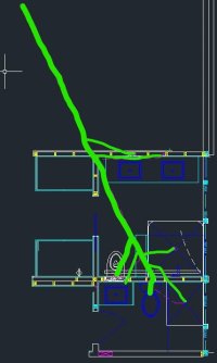
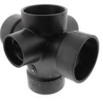
I have a 1963 ranch over a crawl space with back to back Master and Secondary bathrooms. It "was" all copper, but I had to rework the master layout quite a bit and I've now cut most of it out of the way except for the 3" vent and stack right behind the original toilet in bath 2. What was there, was a 4 way brass fitting 3x3x3x3x1.5x1.5. I was looking to more or less mimic that one joint in ABS and be able to tie back into the copper above and below that fitting. I see Nibco makes a

3" x 3" x 3" x 3" x 2" x 2" Hub ABS Double Sanitary Tee with Two 90° Inlets (583599)​

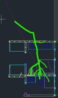
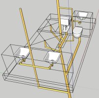
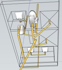
but the new toilet location in the master makes this challenging. I'll wind up having to more or less make a sweeping 90d bend from both WC into it. Then I'll have to run new 2" drains from both showers into the 2" connection points. The sinks tie ie on both sides to more or less equal the load balancing at the Hub. I also have to add a studor on one of the master sinks to get venting on that leg. Any issues with what I've described or in the image attached?

CaptureSketch.JPG
 

Attachments

  • DrainsSketch1.pdf
    19.8 KB · Views: 148
  • CaptureHub.JPG
    CaptureHub.JPG
    13.8 KB · Views: 131
Last edited:

wwhitney

In the Trades
Messages
6,567
Reaction score
1,847
Points
113
Location
Berkeley, CA
Why do you need the quadruple san-tee turned 45 degrees from the principal axes? If this is over a crawl space, are you running any drains between joists, or is everything under the joists? If between the joists, which way do they run?

What does the 3" copper drain do below the remnant vertical portion? It must turn horizontal, is that above grade or below grade? Which way does it run, and have you consider tying one of the bathrooms in downstream of the remnant vertical portion, rather than bringing all 7 fixtures together at one point?

Cheers, Wayne
 

Oilhammer

Member
Messages
35
Reaction score
1
Points
8
Location
Denver
The copper line drops about 5', then turns horizontal and runs across the dirt in the crawl to the upper left corner. It turns to cast iron pretty quickly and I really don't want to mess with that. Otherwise, I'd probably do a horizontal run below the joists as a wet vent, then drop down to the cast iron near the upper left corner of the crawl.

As far as where they tie in, this is how it was before. The only difference is there was only one master vanity and it was all run in 1.5" copper. Well that, and the positions have all changed in the master.

This sketch is if I decided to do the wet vent. I just don't like tying into cast iron...no tools to snap such pipes.

CaptureSketch2.JPG
 

wwhitney

In the Trades
Messages
6,567
Reaction score
1,847
Points
113
Location
Berkeley, CA
There's something to be said for getting rid of all the copper and tying into the cast iron. All you need is to get one square cut, clean off the barrel of any rust/debris/lettering, and use a shielded rubber coupling to adapt to new plastic (if the joint is above grade; or the longer possibly unshielded type if the joint will be buried). You can cut cast iron with a diamond wheel on an angle grinder, or very slowly with a diamond reciprocating saw, either of which would be fine for one cut. My experience is only with new cast iron, though, so it's possible it doesn't apply to 60 year old cast iron.

Or if the copper goes into a leaded joint on an intact cast iron hub, you can drill out the lead (carefully) to remove the copper and leave an intact cast iron hub. Then you can get a rubber donut to insert into the hub, which receives a plastic pipe.

On the wet vent layout you did, which is the dry vented fixture? It needs to be one of the two upstream-most fixtures, and then each wet vented fixture has to join its drain individually--you can't joint two fixtures to be wet vented together, then join their common drain to the drain with the dry vented fixture.

Cheers, Wayne
 

Terry

The Plumbing Wizard
Staff member
Messages
29,942
Reaction score
3,459
Points
113
Location
Bothell, Washington
Website
terrylove.com
I would not use a fitting like that for installing two toilets into the one fitting. With the current toilets that we're installing, the fittings need to be wye fittings where they join together.


Oilhammer

Member
Messages
35
Reaction score
1
Points
8
Location
Denver
There's something to be said for getting rid of all the copper and tying into the cast iron. All you need is to get one square cut, clean off the barrel of any rust/debris/lettering, and use a shielded rubber coupling to adapt to new plastic (if the joint is above grade; or the longer possibly unshielded type if the joint will be buried). You can cut cast iron with a diamond wheel on an angle grinder, or very slowly with a diamond reciprocating saw, either of which would be fine for one cut. My experience is only with new cast iron, though, so it's possible it doesn't apply to 60 year old cast iron.

Or if the copper goes into a leaded joint on an intact cast iron hub, you can drill out the lead (carefully) to remove the copper and leave an intact cast iron hub. Then you can get a rubber donut to insert into the hub, which receives a plastic pipe.

On the wet vent layout you did, which is the dry vented fixture? It needs to be one of the two upstream-most fixtures, and then each wet vented fixture has to join its drain individually--you can't joint two fixtures to be wet vented together, then join their common drain to the drain with the dry vented fixture.

Cheers, Wayne
Oh good point on the wet vent, I forgot about single tie ins. I think the bath 2 shower would bend around to the right and connect first, then Bath 2 toilet, then Bath 2 sink, then master shower, then master toilet, then master lavs. The master toilet and shower hit about the same point, so makes sense to have the shower upstream of the toilet, right? One last thing in that layout, is the Bath 2 lav drain is tough...I might be able to squeeze it to the right of the in-wall toilet, but probably has to go to the left. There's just not much room to deal with back to back fixtures like that. I really wanted to get two in-wall toilets there, but the main vent was in the way.

So to summarize, I think both of you are suggesting I NOT try to duplicate the old layout where everything drops back to the vertical stack. I'd rather lose the studor, so installing a wet vent is the only way to possibly do that. It was also free up the middle of the crawl a bit since I want to dig it out about a foot so I can walk around without bumping my head.

What do you mean about getting rid of the copper? I thought it was in very good shape....this copper is not like the bulk of stuff available in HD these days. It's quite thick and stays shiny. That said, it's really not that difficult to just leave the vent portion copper and demo the rest. I don't "like" working with cast iron, but I've done it. I'd rather deal with cast than clay any day. I don't have a snapper, but an angle grinder with a cutting wheel will take care of it.

Alternate wet vent sketch attached.
 

Attachments

  • CaptureSketch2a.JPG
    CaptureSketch2a.JPG
    879.7 KB · Views: 129
Last edited:

wwhitney

In the Trades
Messages
6,567
Reaction score
1,847
Points
113
Location
Berkeley, CA
Oh good point on the wet vent, I forgot about single tie ins. I think the bath 2 shower would bend around to the right and connect first, then Bath 2 toilet, then Bath 2 sink, then master shower, then master toilet, then master lavs.
The Bath 2 lav needs to be one of the upstream most two fixtures. I.e. if you start at the Bath 2 lav, then each fixture comes into join one at a time, individually. The IPC doesn't care about the order.

A shower trap arm is from the trap to the wye where it joins the horizontal went vent (the drain with the lav). The shower trap arms can not fall more than one pipe diameter (use a 2" drain, so 2"). The WC drains have no such restriction.

The master lavs will need a separate dry vent, as again their vent must come off before the the lav trap arm falls one pipe diameter (1.5" if you use a 1.5" trap). So they can't be wet vented under the floor.

I agree that you should ignore what was there before, and just do a clean sheet design, with the constraints of your fixture locations and the cast iron you need to tie into.

If you excavate the soil in your crawl space, make sure you know where the bottom of your footings are, and do not excavate lower than that without careful consideration.

Cheers, Wayne
 

Oilhammer

Member
Messages
35
Reaction score
1
Points
8
Location
Denver
The Bath 2 lav needs to be one of the upstream most two fixtures. I.e. if you start at the Bath 2 lav, then each fixture comes into join one at a time, individually. The IPC doesn't care about the order.

A shower trap arm is from the trap to the wye where it joins the horizontal went vent (the drain with the lav). The shower trap arms can not fall more than one pipe diameter (use a 2" drain, so 2"). The WC drains have no such restriction.

The master lavs will need a separate dry vent, as again their vent must come off before the the lav trap arm falls one pipe diameter (1.5" if you use a 1.5" trap). So they can't be wet vented under the floor.

I agree that you should ignore what was there before, and just do a clean sheet design, with the constraints of your fixture locations and the cast iron you need to tie into.

If you excavate the soil in your crawl space, make sure you know where the bottom of your footings are, and do not excavate lower than that without careful consideration.

Cheers, Wayne
I neglected to mention that Bath 2 vanity has a dedicated vent that taps into the 3" copper main vent. I could rotate the wet vent clockwise to get the trap arms shorter on everything, then turn the whole thing back towards the cast iron crawl run. More like this?

As far as digging out the crawl, it's just a walk path down the middle to the HVAC. It's also not a normal crawl...it's on caissons so no footings by normal standards. But you are referring to side loading the walls with soil pressure, which I should be fine on. Two of the walls are nearly fully daylighted already and I'm not getting anywhere near the others.
 

Attachments

  • CaptureSketch2B.JPG
    CaptureSketch2B.JPG
    880.2 KB · Views: 124

wwhitney

In the Trades
Messages
6,567
Reaction score
1,847
Points
113
Location
Berkeley, CA
Yes, the Bath 2 vanity needs a dry vent to wet vent vent other fixtures. If the horizontal crawl space drains are all below the joists, then a typical layout for the Bath 2 vanity to wet vent the two WCs and the two showers might be something like the drawing below (as far as the horizontal drains).

The double vanities need a separate dry vent (one vent can be used for both in various ways), and the joint drain can join in anywhere.

Cheers, Wayne


CaptureSketch.JPG
 

Oilhammer

Member
Messages
35
Reaction score
1
Points
8
Location
Denver
Ok, thanks for all the help. I can add a studor on the master vanity and tie those two together for venting there. How do you envision the main 3" dry vent connecting to the horizontal wet vent leg in this? (That's the 3" white circle immediately behind the blue toilet). It has a 1.5" vent arm that comes over to the Bath 2 vanity already.
 

wwhitney

In the Trades
Messages
6,567
Reaction score
1,847
Points
113
Location
Berkeley, CA
How do you envision the main 3" dry vent connecting to the horizontal wet vent leg in this? (That's the 3" white circle immediately behind the blue toilet).
Two possibilities:

1) One is that it doesn't have to. The lav san-tee has a drain going down below the floor that joins the WC drain as drawn, and a vent that rises up and then jogs over to connect to the 3" going through the ceiling. The IPC would allow those both to be 1.5", although I'm used to the 2" that the UPC requires.

2) The other is that you can eliminate the under floor individual lav drain. The 3" stack stays at the white circle or moves a little left or right (same stud bay). The 1-1/2" lav trap arm runs horizontally in the wall to hit the 3" stack (max fall between trap and stack connection is 1-1/2"). Then the stack connects to the horizontal WC drain: if the stack is directly on top of the WC drain, via an upright combo; if it's next to it, via a LT90 pointed at the branch inlet of a horizontal wye (which works best with a particular minimum left-right offset).

Cheres, Wayne
 

Oilhammer

Member
Messages
35
Reaction score
1
Points
8
Location
Denver
Threw this into 3D as a rough sketch. No slope to pipes and no rotated fittings....just visualizing the run.
As I look at this, doesn't it make sense to move the main horizontal run to align with the 3" vent but extend backwards a bit for a cleanout? That means the toilet would angle in to the wet vent instead of being straight. I more or less drew your sketch, but trying to sort out a cleanout that isn't blocked.
 

Attachments

  • 3dsketch1.JPG
    3dsketch1.JPG
    94 KB · Views: 121
  • 3dsketch2.JPG
    3dsketch2.JPG
    87 KB · Views: 119

wwhitney

In the Trades
Messages
6,567
Reaction score
1,847
Points
113
Location
Berkeley, CA
As I look at this, doesn't it make sense to move the main horizontal run to align with the 3" vent but extend backwards a bit for a cleanout?
Sounds fine, a good way to get a cleanout that's not directly under the WC. The WC can join the line running under the 3" stack via a wye; one possibility is a flat (2% slope) wye with a closet bend (same radius as a quarter bend), or a LT90, the outlet of which is pointed at the branch inlet on the wye. Or you could roll the wye up 45 degrees and then use a 60 degree bend to go vertical under the closet flange. Which of those are feasible will depend on the exact left-right offset.

Either way, the lav is no longer wet venting the WC, the stack is dry venting the WC. But that's fine, and the two showers are still wet vented by either the lav or the WC, or both, depending on your point of view.

Cheers, Wayne
 

Reach4

Well-Known Member
Messages
38,892
Reaction score
4,436
Points
113
Location
IL
Feed the upper left shower in before the VTR.

The extra vent around to the toilet will then not be needed.
 

Oilhammer

Member
Messages
35
Reaction score
1
Points
8
Location
Denver
I can extend the cleanout in the 3" horizontal run back some. Then tie the 2" bath 2 shower in before the VTR comes down? That's easy. The vented toilet is more a way to drain the sink for bath 2 than a vent. Just as easy to run Bath 2 sink to the horizontal 3" between toilet 2 and m toilet.

In 2D, it's starting to look like this:
1645566024946.png


Or perhaps much closer to Wayne's original sketch like this:
1645566640500.png

Thanks for all the advice. It should be obvious I don't do this for a living!
 
Last edited:

wwhitney

In the Trades
Messages
6,567
Reaction score
1,847
Points
113
Location
Berkeley, CA
The extra vent around to the toilet will then not be needed.
That's not a vent around the toilet, that's the lav drain.

Now that you are feeding the shower in between the cleanout and the 3" stack, then the stack dry vents the shower. Then the lav wet vents the WC. The lav and/or shower wet vent the downstream shower and WC.

Note that in your rendering it looks like the wyes where the showers join the 3" drain are rolled up a little. They need to be flat (2% slope), not rolled up at all. Lower the shower traps or raise the 3" drain as required to achieve that. On the WC, it doesn't matter.


Cheers, Wayne
 

wwhitney

In the Trades
Messages
6,567
Reaction score
1,847
Points
113
Location
Berkeley, CA
The rule (trap weir rule) that applies to the showers (and any fixture with an external trap, like lavs) is that the vent connection has to occur before the drain (trap arm) falls one pipe diameter. That avoid siphoning.

With wet venting and a wye, the vent connection is at the "crotch" of the wye. So rolling the wye just gives you extra drop on the trap arm and possibly violates the trap weir rule. The wyes should be flat, there's no upside to rolling them.

WCs don't have to comply with the trap weir rule, so their wyes could be rolled if desired.

Now if the straight portion of a wye is a trap arm, and the side branch is a dry vent take off, then the wye needs to be rolled at least 45 degrees, as a dry vent takeoff has to be vertical (at most 45 degrees off plumb) and stay vertical until 6" above the fixture flood rim. Does not apply to a wet vent, but would apply to one way of venting the double lavs. Although that's all in a wall, so the wye would be upright anyway.

Cheers, Wayne
 

Oilhammer

Member
Messages
35
Reaction score
1
Points
8
Location
Denver
I got the Geberit in-wall unit installed and that's a pretty slick setup for saving space. These bathrooms are so tiny, it makes me start thinking about using one in Bath 2 as well. If I did that, the 3" VTR is in the way. I can't change the roof penetration (flat roof, very risky) but any reason I can't cut the 3" copper back to about 12" below the roof and put a 3x2x2 on it? I could then branch over to the Bath 2 sink for venting there, and run the other 2" around the in-wall toilet and tie it into one of the shower drains. 3x1.5x1.5 would be ideal to keep from boring the studs too much and making it flex. Those in-walls need stout framing!

1646236405739.png


I need to make sure the framing can fit with the units and the Bath 2 sink drain....it's going to be tight. Speaking of tight, Mbath sink drain (red part) needs to be 2" or can it be 1.5? I have to miss a floor joist directly under the wall. I might be able to squeak 1.5 but 2" will clearly push the drain out of the wall at the floor to avoid getting into the joist.
 
Last edited:
Top
Hey, wait a minute.

This is awkward, but...

It looks like you're using an ad blocker. We get it, but (1) terrylove.com can't live without ads, and (2) ad blockers can cause issues with videos and comments. If you'd like to support the site, please allow ads.

If any particular ad is your REASON for blocking ads, please let us know. We might be able to do something about it. Thanks.
I've Disabled AdBlock    No Thanks