Pitless adapter, Is this salvageable?

Users who are viewing this thread

Reach4

Well-Known Member
Messages
38,893
Reaction score
4,436
Points
113
Location
IL
Pressure tank is a fiberglass Wellmate with bladder.
So any check valves much above the pump should be removed. Any bleeder valves should be removed.

If the Wellmate pressure tank with a bladder fails, you would want to go to a similar looking and working tank with a diaphragm rather than a bladder. The diaphragms tend to be longer lived.

Myers pump that had mud covering over half of the intake. I thought there was a check valve above it but could be wrong. I didn't look that close at it.
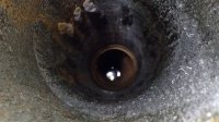
Pumps would often have a check valve built in. Even if there is a check valve in the pump, it is OK to put one a little above the pump.

Maybe you could get the well cleaned out. The fast way is with a big engine-driven compressor blowing air. Maybe 200 cfm give or take. The debris shoots up like a geyser. The slower way uses a much smaller (maybe 5 or so cfm) compressor and an air lift pump (usually homemade). An air lift pump needs some proportion of the casing to be filled with water.
 

Whatnot

Member
Messages
57
Reaction score
0
Points
6
Location
Wisconsin
I got a few more details but haven't really done anything with it yet. The unit was made by Baker but I can't find any part numbers on it. Inside the cap is PK 136
The casing above ground is 6" ID and 6-5/8"" OD. The casing below the pitless is also 6" ID.
Water level in well is currently down 20 feet from surface. I only had a 100' tape measure and it did not reach the bottom. Old pump had 70' of pipe, so bottom of pump was around 80' I am thinking I will just put new pump at same depth. Is there any reason to change that?

Do I need to wire brush the casing all the way down to the spool position? If not how do you keep from damaging the new o-rings when dropping it back in?

I tried to take a picture of inside the well casing. Can't really see much though.
Also, got power usage stats showing when pump was running continuous. (gauge in house was 2psi)
 

Attachments

  • well.jpg
    well.jpg
    84.2 KB · Views: 382
  • power usage.png
    power usage.png
    112.3 KB · Views: 299

Reach4

Well-Known Member
Messages
38,893
Reaction score
4,436
Points
113
Location
IL
Do I need to wire brush the casing all the way down to the spool position? If not how do you keep from damaging the new o-rings when dropping it back in?
6 inch casing. How big is the 0-ring groove and o-ring? I would think the casing ID is bigger. So I would try to minimize dragging the lubed o-rings on the casing on the way down.

Lube the O-rings with silicone. Usually you use a very thin layer, but I might go a bit heavier for this job.

I like Molykote 111. A 5.3 ounce tube will last a long long time. Many prefer something like Dow Corning 7 Release Compound, which is from the same company, and is a tad less viscous. http://www.dowcorning.com/applications/search/default.aspx?R=386EN

I like the thicker for non pro use. It may be a little slower to apply. I wear nitrile gloves to make hand cleaning easier. I have not done pump pulling, but if I did, I would use the silicone compound.

Is there much sediment? It is possible to clean a well. A big (175 to 275 cfm) engine-driven compressor can drive air down a 1 inch pipe to the bottom, and blow stuff up like a geyser. It might be $800 or more to have than done professionally, and those big compressors are not cheap to rent. For slower home use, there are air lift pumps. Those need a high-enough static level. I am not saying your well needs cleaning.
 

LLigetfa

DIYer, not in the trades
Messages
7,507
Reaction score
581
Points
113
Location
NW Ontario, Canada
I thought Baker spools had a smaller casing below the spool that the spool rested on. What holds the spool in the right spot?
 

Reach4

Well-Known Member
Messages
38,893
Reaction score
4,436
Points
113
Location
IL
I thought Baker spools had a smaller casing below the spool that the spool rested on. What holds the spool in the right spot?
It may be something similar to this. In that case, I think trying to clean the upper casing while minimizing what you knock down the well could be worthwhile. Or maybe just let the brushed rust fall down, and run the water to the ditch for a good while after starting the pump up. You generally want to do that after pulling a pump anyway. I might even go far as to try to grease up the walls of the casing. I don't know. Just an idea. By design, the O-ring may not scrape the sides. That seems to be what the o-ring protector does -- holds the o-rings away from contacting the casing.

standard_industrial.gif
 

Whatnot

Member
Messages
57
Reaction score
0
Points
6
Location
Wisconsin
I stopped at a plumber today that works on wells to see if they o-rings and they said the spool was not usable. I hadn't looked that close at the pipe fitting before but it is rusted really bad. He said it was for a drain back system and the bleeder is shot too.
Apparently someone just stuck in the bladder tank and got rid of the air control stuff in the house.
 

Whatnot

Member
Messages
57
Reaction score
0
Points
6
Location
Wisconsin
I thought Baker spools had a smaller casing below the spool that the spool rested on. What holds the spool in the right spot?

There is a lip that it sits on. I put it in without the o-rings and does stop it from going in further. It steps back out below the lip the same diameter.

If I put in a standard pitless, I will probably go down a little lower. The existing one seems like it was a little too shallow. I am hoping the lip for the spool doesn't stick out too much and get in the way of the lift pipe.
 

Whatnot

Member
Messages
57
Reaction score
0
Points
6
Location
Wisconsin
6 inch casing. How big is the 0-ring groove and o-ring? I would think the casing ID is bigger. So I would try to minimize dragging the lubed o-rings on the casing on the way down.
O-ring is 6" OD and 1/4" diameter
 

VAWellDriller

Active Member
Messages
539
Reaction score
111
Points
43
Location
Richmond, VA
I got a few more details but haven't really done anything with it yet. The unit was made by Baker but I can't find any part numbers on it. Inside the cap is PK 136
The casing above ground is 6" ID and 6-5/8"" OD. The casing below the pitless is also 6" ID.
Water level in well is currently down 20 feet from surface. I only had a 100' tape measure and it did not reach the bottom. Old pump had 70' of pipe, so bottom of pump was around 80' I am thinking I will just put new pump at same depth. Is there any reason to change that?

Do I need to wire brush the casing all the way down to the spool position? If not how do you keep from damaging the new o-rings when dropping it back in?

I tried to take a picture of inside the well casing. Can't really see much though.
Also, got power usage stats showing when pump was running continuous. (gauge in house was 2psi)

I think you'll find if you dig this up all the way, you have 5" casing....Baker Units upper casing is always 1 pipe size bigger. Your post below says plumber says you can't reuse the spool. I think you should take out all the rusty reducer fittings on the pump side and try it again. It will be a lot of work to put on a new pitless.

Its best to brush the upper casing if you can....if you can't brush it, just run some water knock off any loose scale. Lube the orings with silicone and be careful to lower it straight down the hole.
 

Whatnot

Member
Messages
57
Reaction score
0
Points
6
Location
Wisconsin
Ok, I will try getting it apart. I am 99% sure the casing is the same size below and above the spool area. Is it possibly to adapt it so the 5" goes right back to 6"? I might need to get a camera down there to look at it better.
 

Reach4

Well-Known Member
Messages
38,893
Reaction score
4,436
Points
113
Location
IL
Ok, I will try getting it apart. I am 99% sure the casing is the same size below and above the spool area. Is it possibly to adapt it so the 5" goes right back to 6"? I might need to get a camera down there to look at it better.
Why would it matter to you whether the casing below was 5 or 6? I can think of a reason I might want to know, but I doubt it is one you were thinking of.
 

VAWellDriller

Active Member
Messages
539
Reaction score
111
Points
43
Location
Richmond, VA
Ok, I will try getting it apart. I am 99% sure the casing is the same size below and above the spool area. Is it possibly to adapt it so the 5" goes right back to 6"? I might need to get a camera down there to look at it better.

You can get weld fittings to make the casing any size you want...but why would you want to change it?
 

Whatnot

Member
Messages
57
Reaction score
0
Points
6
Location
Wisconsin
Why would it matter to you whether the casing below was 5 or 6? I can think of a reason I might want to know, but I doubt it is one you were thinking of.
It wouldn't unless I end up putting in a regular style pitless adapter and the area where the spool was gets in the way of the lift pipe threads.
I just mentioned it because of the posts that said it is always smaller and that does not appear to be the case on this one.
 

Whatnot

Member
Messages
57
Reaction score
0
Points
6
Location
Wisconsin
It was much easier that expected to get the drop pipe fittings out.
The fitting in the picture is what the plumber said was broken. Do I need to remove that and put in a plug?

spool no pipe.jpg
 

Valveman

Cary Austin
Staff member
Messages
14,633
Reaction score
1,304
Points
113
Location
Lubbock, Texas
Website
cyclestopvalves.com
It was much easier that expected to get the drop pipe fittings out.
The fitting in the picture is what the plumber said was broken. Do I need to remove that and put in a plug?

Yes that looks like a bleeder orifice, so remove it and plug the hole to use a diaphragm style tank.
 

Reach4

Well-Known Member
Messages
38,893
Reaction score
4,436
Points
113
Location
IL
It cleaned up really nice.

Click Inbox.

In post #10, VAWellDriller said that the little door (B in photo) is a check valve could be removed. It is probably a good idea to remove that even if the door is not sticking.

I don't know if there is another non-bottom check valve, but if so, that would be removed too.

img_2.jpg
 
Last edited:

Whatnot

Member
Messages
57
Reaction score
0
Points
6
Location
Wisconsin
What you marked with A in the above picture is what I was told was broken. Does that need to be removed?
 

Reach4

Well-Known Member
Messages
38,893
Reaction score
4,436
Points
113
Location
IL
Do any of these sizes look right?
If you are measuring the groove diameter, I would think no, but I cannot be sure. You show 5.375 inches. Are these things usually stretched that much when installed? I was not thinking so. If you were actually measuring the outside of the groove (piston diameter), then yes, NC15 might be right but then I would wonder if there would be enough to fill the extrusion gap.
piston-concentric.svg

http://www.applerubber.com/oring-gland-calculator/
 
Last edited:
Top
Hey, wait a minute.

This is awkward, but...

It looks like you're using an ad blocker. We get it, but (1) terrylove.com can't live without ads, and (2) ad blockers can cause issues with videos and comments. If you'd like to support the site, please allow ads.

If any particular ad is your REASON for blocking ads, please let us know. We might be able to do something about it. Thanks.
I've Disabled AdBlock    No Thanks