OK just received a well report on this system. Shows a static water level of 160' and a pumping level of 220'. With the 25 GPM, 2HP pump only able to build 56 PSI from 220' I think we have figured this out. The pump will not shut off because the pressure can never get to 60 PSI. This will get the water hot and melt the casing. Wrong pump for that depth caused a lot of problems.
You are using an out of date browser. It may not display this or other websites correctly.
You should upgrade or use an alternative browser.
You should upgrade or use an alternative browser.
Check valve bad, burnt up well motor
- Thread starter Marcella Bonner
- Start date
Users who are viewing this thread
Total: 2 (members: 0, guests: 2)
VAWellDriller
Active Member
OK just received a well report on this system. Shows a static water level of 160' and a pumping level of 220'. With the 25 GPM, 2HP pump only able to build 56 PSI from 220' I think we have figured this out. The pump will not shut off because the pressure can never get to 60 PSI. This will get the water hot and melt the casing. Wrong pump for that depth caused a lot of problems.
Possible explanation but not likely - Did the report say what depth the pump was set? Assuming that info is correct, 160 static, 220 pumping at 25 gpm. You need think about whats going on in the system as a whole right before shutoff before blaming the pump. If it pumped it down to 220, at 25 gpm and then someone instantly stopped using water, the water level in the well would rise at about 10' per minute in the well and the pump could reach shutoff (we are guessing set at 60). I see folks set pump what seems to be too deep a lot.....but you have to remember that there is a point where yield and recovery of the well, beat the pump curve. Fact is IF those yield numbers are correct, this pump could not overpump that well even if it was set at 300'. Pump output could only beat well yield when water level was between 220 and 240'....then the pump output would drop off.....as the pump output dropped off, the water level will rise. It's almost like who's on 1st. water level too deep, pump output reduces...pump output reduces, water level rises in the well.
Sponsor
Paid Advertisement
Marcella Bonner
New Member
I would sincerely like to thank each one of you Valveman, VaDriller and the rest of you good folks. I am just getting in from loading three 55gallon drums of water and bucketing them across a field for the horse barn and am worn out. I have sat and waited for the original driller to show up this morning at 8am. And guess what...NO SHOW. So I called the salesman again, and I guess he got sick of hearing my voice mail messages and forwarded my message onto the VP. The vice president of the company called me and said that they aren't coming--you really don't want to know what was said after that.
The pump is dead and it is 4months out of warranty and it is my problem is what he informed me. They aren't coming and have no intention of coming. I told him that would have been nice to know 3 days ago. No joke, this is exactly what was said. I told him this was unacceptable and that I am sure Franklin Electric would honor their pump even if it was 4 months out of warranty, the driller said NO he won't. I asked for Franklin Electric salesman 's name.
I called Mr. Jim Hartman (salesman at Franklin Electric) and he said, he would not be calling the driller to come diagnose the problem but he might be able to warranty the pump if we know what happened. I said to him that Allied Well (this is the driller) refuses to come and actually determine what happened. I again asked Mr. Hartman to call Allied Well on my behalf to tell him you may warranty the pump anyways and he said no.
So I called Allied Well and asked him to Diagnose the problem. He said for $210/hr he will see what happened but he will not be giving warranty on the pump whatsoever nor crediting the labor cost of pulling up the pump and hung up on me twice!!. Needless to say. I am very angry. I do not mean to use the actual names of these companies but to some extent I think you need to know what some of these people are doing. It is a true disgrace.
I called the Maryland Department of Environment to ask what in the hell is going on. I spoke to the construction well department (a Geologist of some sort who said to me, frankly, I would file a complaint against Allied Well, this is very unfortunate situation but I strongly urge you to complain so that they stop this BS. He gave me all of the info for the President of the Board. I left an email and voice message for her.
So tomorrow, I will file a complaint with the Maryland Board of Drillers. Since I am on the front lines for the COVID thing I guess I will find some time to do this in between filling 55 gallon drums for 8 horses. I think this is very poor business. Needless to say I am still out of water.
I have called an unrelated driller to come out and I will pay his fees to help me figure out what to do if he agrees to do this, I left a voice mail at his office and hopefully he will call tomorrow. I really don't know what to do. I think the only thing I can do is drill a new well. I just don't want to make the same mistake twice, I relied on the contractor to do the right thing, but maybe that was not what should have been done.
I think from what Valveman is suggesting that the pump, the casing, the everything was wrong. VA Driller you don't seem to agree. VA Driller-I don't understand the whole thing you wrote back to Valveman but seems like what you are saying is that sometimes the text book is not correct, that the pump may end up getting cooled if water rising fast enough despite what the the curve states, that seems plausible but would the water rise fast enough all of the time to cool the pump or just some of the time and that is why the pump has lasted for 1.5yrs instead of breaking sooner.
I think Valveman, seemed like you hit the nail on the head with the PSI. About 6months after the well was drilled the control box went out, but the pump was never checked. The driller thought it was the pump. I wonder if this has been failing from the get go.
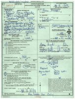
The pipe size was chosen by the driller. I don't know all of your terminology but I have included a copy of the final well report that states the pump is set at 220.' Maybe it doesn't say that but something is at 220ft.
I learned today that we also have a cycle stop valve and worked closely with Carey Austin in Texas--he is great help on our house well that was drilled 5yrs ago, we called him for some help on this issue and he says your exact stuff Valveman--duh, Valveman it is you!! Well kudos to all of your great help!
Anyways, I do appreciate all of you and thank you for allowing me to be a part of the forum, it has been helpful. I feel like I may now be able to make some intelligent decisions on my next well or pump whichever it may be. If you have any other suggestions, that will be appreciated. I will probably be spending my money on a well and not an attorney because I can't afford both. Allied well wins again.
I think.

The pump is dead and it is 4months out of warranty and it is my problem is what he informed me. They aren't coming and have no intention of coming. I told him that would have been nice to know 3 days ago. No joke, this is exactly what was said. I told him this was unacceptable and that I am sure Franklin Electric would honor their pump even if it was 4 months out of warranty, the driller said NO he won't. I asked for Franklin Electric salesman 's name.
I called Mr. Jim Hartman (salesman at Franklin Electric) and he said, he would not be calling the driller to come diagnose the problem but he might be able to warranty the pump if we know what happened. I said to him that Allied Well (this is the driller) refuses to come and actually determine what happened. I again asked Mr. Hartman to call Allied Well on my behalf to tell him you may warranty the pump anyways and he said no.
So I called Allied Well and asked him to Diagnose the problem. He said for $210/hr he will see what happened but he will not be giving warranty on the pump whatsoever nor crediting the labor cost of pulling up the pump and hung up on me twice!!. Needless to say. I am very angry. I do not mean to use the actual names of these companies but to some extent I think you need to know what some of these people are doing. It is a true disgrace.
I called the Maryland Department of Environment to ask what in the hell is going on. I spoke to the construction well department (a Geologist of some sort who said to me, frankly, I would file a complaint against Allied Well, this is very unfortunate situation but I strongly urge you to complain so that they stop this BS. He gave me all of the info for the President of the Board. I left an email and voice message for her.
So tomorrow, I will file a complaint with the Maryland Board of Drillers. Since I am on the front lines for the COVID thing I guess I will find some time to do this in between filling 55 gallon drums for 8 horses. I think this is very poor business. Needless to say I am still out of water.
I have called an unrelated driller to come out and I will pay his fees to help me figure out what to do if he agrees to do this, I left a voice mail at his office and hopefully he will call tomorrow. I really don't know what to do. I think the only thing I can do is drill a new well. I just don't want to make the same mistake twice, I relied on the contractor to do the right thing, but maybe that was not what should have been done.
I think from what Valveman is suggesting that the pump, the casing, the everything was wrong. VA Driller you don't seem to agree. VA Driller-I don't understand the whole thing you wrote back to Valveman but seems like what you are saying is that sometimes the text book is not correct, that the pump may end up getting cooled if water rising fast enough despite what the the curve states, that seems plausible but would the water rise fast enough all of the time to cool the pump or just some of the time and that is why the pump has lasted for 1.5yrs instead of breaking sooner.
I think Valveman, seemed like you hit the nail on the head with the PSI. About 6months after the well was drilled the control box went out, but the pump was never checked. The driller thought it was the pump. I wonder if this has been failing from the get go.
The pipe size was chosen by the driller. I don't know all of your terminology but I have included a copy of the final well report that states the pump is set at 220.' Maybe it doesn't say that but something is at 220ft.
I learned today that we also have a cycle stop valve and worked closely with Carey Austin in Texas--he is great help on our house well that was drilled 5yrs ago, we called him for some help on this issue and he says your exact stuff Valveman--duh, Valveman it is you!! Well kudos to all of your great help!
Anyways, I do appreciate all of you and thank you for allowing me to be a part of the forum, it has been helpful. I feel like I may now be able to make some intelligent decisions on my next well or pump whichever it may be. If you have any other suggestions, that will be appreciated. I will probably be spending my money on a well and not an attorney because I can't afford both. Allied well wins again.
I think.
Attachments
Last edited:
VAWellDriller
Active Member
What I was saying was working directly with the pump curve and the yield numbers Valveman had posted (which were not in line with the report your just posted)....no fuzzy or funny math or anything. I think that when Valveman reads my post and thinks about it, he will certainly agree. Aside from that your well log indicates an 80 gpm yield with 160 static and 220 pumping level after 2 hours of airlift development; which IF that is true, this pump was entirely appropriate for the application....he should agree on that too. As far as casing, your state regulators can tell you what is approved and what is not approved. The completion report says 4.5" nominal casing.....which is a lot better than 4", but still susceptible to heat damage under the wrong circumstances.
You are in a terrible position, no doubt.....the driller may be entirely to blame...or it may just be a perfect storm of bad luck. There are a lot of details and unknowns to figure out. Hearing your side of the story, I definitely think the driller should be more responsive in trying to resolve this. You should go ahead with filing complaints...that's the only way anything ever gets fixed.
You are in a terrible position, no doubt.....the driller may be entirely to blame...or it may just be a perfect storm of bad luck. There are a lot of details and unknowns to figure out. Hearing your side of the story, I definitely think the driller should be more responsive in trying to resolve this. You should go ahead with filing complaints...that's the only way anything ever gets fixed.
Marcella Bonner
New Member
What I was saying was working directly with the pump curve and the yield numbers Valveman had posted (which were not in line with the report your just posted)....no fuzzy or funny math or anything. I think that when Valveman reads my post and thinks about it, he will certainly agree. Aside from that your well log indicates an 80 gpm yield with 160 static and 220 pumping level after 2 hours of airlift development; which IF that is true, this pump was entirely appropriate for the application....he should agree on that too. As far as casing, your state regulators can tell you what is approved and what is not approved. The completion report says 4.5" nominal casing.....which is a lot better than 4", but still susceptible to heat damage under the wrong circumstances.
You are in a terrible position, no doubt.....the driller may be entirely to blame...or it may just be a perfect storm of bad luck. There are a lot of details and unknowns to figure out. Hearing your side of the story, I definitely think the driller should be more responsive in trying to resolve this. You should go ahead with filing complaints...that's the only way anything ever gets fixed.
Marcella Bonner
New Member
The state regulator today, told me that there is no regulation on the casing size. Nor is the well driller really on site, nor is anyone every really checking those numbers on the well report. No doubt the driller's license is listed but who really knows who was really there and if those numbers are what should be there pumping vs. what is really there pumping. Really is pathetic. State regulator guy today agreed with me, no oversight whatsoever, best part is, Allied Well knows this and have gotten away with it. Geez. So one more question VA driller, after reading the completion well report, in your opinion, do you think the PSI theory lis ikely-you mention some of his numbers weren't the same as the report? How do you know what psi the pump is set on? from the manufacturer?
Last edited:
VAWellDriller
Active Member
I don't agree with valvemans post....and I think once he reads my explanation and the report he will agree that the pump was appropriate for the well as it was reported on the form.
The pressure is set by the either the pressure switch which would be located on or near the tank.....or by a VFD. You mentioned a control box that needed replacement indicates you have a mechanical pressure switch. Some folks may call a VFD a control box so I'm just not sure to which you were referring.
As far as regulation...MD has a ton of regulations....they may not be actively out checking behind people but I would think in this sort of case they could/would step in.
Marcella Bonner
New Member
I don't agree with valvemans post....and I think once he reads my explanation and the report he will agree that the pump was appropriate for the well as it was reported on the form.
The pressure is set by the either the pressure switch which would be located on or near the tank.....or by a VFD. You mentioned a control box that needed replacement indicates you have a mechanical pressure switch. Some folks may call a VFD a control box so I'm just not sure to which you were referring.
As far as regulation...MD has a ton of regulations....they may not be actively out checking behind people but I would think in this sort of case they could/would step in.
Would that accept a flow inducer sleeve made of sewer pipe over a 4 inch pump? I could see some construction where he sleeve is attached above the pump, avoiding the extra width of a worm gear clamp worm.The completion report says 4.5" nominal casing.....which is a lot better than 4",
Maybe the new pump would be a 3 inch with a 3 inch flow inducer, if the casing has become narrowed because of heat.
Marcella Bonner
New Member
The box I am referring to says Franklin Electric and has some electric things inside--sorry I sound like a kindergartner. I just remembered that the independent contractor said the overload buttons on the box were tripped. (Not the breaker, some sort of button on the box). Not that this helps you with anything but just sayin. There is a pressure switch-I think I remember something about that. I will look at it tomorrow. I wonder if I can see what the pressure was previously set to?
If you are interested I will let you know what my new contractor says if he calls me back and what the Board of Drillers says. I have some time set aside I am hoping he can diagnose or look at the issue and we can get started with correction. Hopefully we will have water next week.
There are nothing but regulations here in Maryland!
What is the model ? That may be on the front panel.The box I am referring to says Franklin Electric
I got pictures of the 2HP standard control box and the 25 GPM, 2HP pump/motor. The static water level is at 160'. They used air lift to determine the pumping level of 220', which I don't think is very accurate. They are probably about as good at drilling as they are at picking the right pump? I agree with VA that the water level should rise when the flow is reduced, but there is no question the pump got hot, so apparently that didn't happen. Because it takes 139' of head to make 60 PSI, with a pump that only builds 340' of head, a water level of 201' would keep the pump from reaching the 60 PSI shut off. And even though it should be able to reach 60 with a water level lower than 201', the flow rate at that point would be so low the pump would get hot anyway. That pump is just working too close to its deadhead pressure, which is what gets the water hot. The CSV chart for acceptable pumps shows a 25GPM, 2HP will work with a water level from 0' to 160'. If the water is deeper than 160' the flow rate will be so low before the pressure gets to 60 the pump will get hot. See the chart here. https://cyclestopvalves.com/pages/pk1a-pside-kick-typical-applications
Also here is the letter from the driller claiming cycling with a small tank is what caused the pump to get hot. A cycling pump is still moving water and the casing will not get hot. Cycling may destroy the internals of a pump/motor, but it won't get the casing hot like a complete lack of flow does. As is the case many times, this driller is blaming the CSV trying to cover his butt. For 28 years Cycle Stop Valves have been making pumps last longer. There has never been a single pump destroyed by a properly installed CSV. When installed with the right pump at the right depth, there is no way to cause a pump to heat up or cycle more than industry standard with the CSV and a small tank.
Dear Sir,
Please see below from the Franklin manual. The manual is attached for your reference.
Frequency of Starts
The average number of starts per day over a period of months or years influences the life of a submersible pumping system. Excessive cycling affects the life of control components such as pressure switches, starters, relays, and capacitors. Rapid cycling can also cause motor spline damage, bearing damage, and motor overheating. All these conditions can lead to reduced motor life. The pump size, tank size, and other controls should be selected to keep the starts per day as low as practical for longest life. The maximum number of starts per 24-hour period is shown in Table 3. Motors should run a minimum of one minute to dissipate heat build up from starting current. Six inch and larger motors should have a minimum of 15 minutes between starts or starting attempts.
Because you have an undersized tank, the pump is not able to run long enough to cool properly.
I confirmed with the Franklin Motors rep that the pump, due to the above condition, would not be eligible for warranty replacement.
Please let us know if you would like us to schedule a service call to replace the system.
Thanks.
Brett Sweeney
Vice President

Allied Well Drilling
Because you have an undersized tank, the pump is not able to run long enough to cool properly.
This is a ridiculous statement. Cycling can cause a lot of problems, but heating the casing is not one of them. When the flow rate is so low the water gets hot, the pump can lose prime, and even an increasing water level won't get the pump primed again until it it turned off and back on. There is no doubt what happened to this pump. However, even if you could get it out Franklin will not warranty it. They will look at it and it will be easy to determine that it was a lack of flow issue, not cycling, and warranty will be denied. The lack of flow issue is the cause of the pump installer not Franklin. Pumps have to be set with the correct water level, pressure settings, and in such a way as they get proper flow past the motor, and that did not happen in this case.
Also here is the letter from the driller claiming cycling with a small tank is what caused the pump to get hot. A cycling pump is still moving water and the casing will not get hot. Cycling may destroy the internals of a pump/motor, but it won't get the casing hot like a complete lack of flow does. As is the case many times, this driller is blaming the CSV trying to cover his butt. For 28 years Cycle Stop Valves have been making pumps last longer. There has never been a single pump destroyed by a properly installed CSV. When installed with the right pump at the right depth, there is no way to cause a pump to heat up or cycle more than industry standard with the CSV and a small tank.
Dear Sir,
Please see below from the Franklin manual. The manual is attached for your reference.
Frequency of Starts
The average number of starts per day over a period of months or years influences the life of a submersible pumping system. Excessive cycling affects the life of control components such as pressure switches, starters, relays, and capacitors. Rapid cycling can also cause motor spline damage, bearing damage, and motor overheating. All these conditions can lead to reduced motor life. The pump size, tank size, and other controls should be selected to keep the starts per day as low as practical for longest life. The maximum number of starts per 24-hour period is shown in Table 3. Motors should run a minimum of one minute to dissipate heat build up from starting current. Six inch and larger motors should have a minimum of 15 minutes between starts or starting attempts.
Because you have an undersized tank, the pump is not able to run long enough to cool properly.
I confirmed with the Franklin Motors rep that the pump, due to the above condition, would not be eligible for warranty replacement.
Please let us know if you would like us to schedule a service call to replace the system.
Thanks.
Brett Sweeney
Vice President
Allied Well Drilling
Because you have an undersized tank, the pump is not able to run long enough to cool properly.
This is a ridiculous statement. Cycling can cause a lot of problems, but heating the casing is not one of them. When the flow rate is so low the water gets hot, the pump can lose prime, and even an increasing water level won't get the pump primed again until it it turned off and back on. There is no doubt what happened to this pump. However, even if you could get it out Franklin will not warranty it. They will look at it and it will be easy to determine that it was a lack of flow issue, not cycling, and warranty will be denied. The lack of flow issue is the cause of the pump installer not Franklin. Pumps have to be set with the correct water level, pressure settings, and in such a way as they get proper flow past the motor, and that did not happen in this case.
VAWellDriller
Active Member
Obviously it was cycling a lot to kill a control box...maybe the csv wasnt installed right.
Obviously it was cycling a lot to kill a control box...maybe the csv wasnt installed right.
Yeah so if the CSV was set too high and not even working the small tank would cause lots of cycling. But it would have still been moving water and not have melted the casing. Cycling should have also tripped the overload in the control box? The pump apparently lost prime more than once, as they noticed dirty hot water and even "steam" a few weeks prior. Cycling will not cause that. No matter if the CSV was set properly or not, that pump lost prime when it wasn't able to build to 60 PSI because of the water level.
LLigetfa
DIYer, not in the trades
How many gallons of the same water would have been moving up and down with the small tank and a failed check valve? Moving the same water back and forth would in theory be the same as recirculating the same water as in the case of a split drop pipe.Cycling can cause a lot of problems, but heating the casing is not one of them.
One interesting data point is that the pump got stuck 12 feet up from where it was hung. Why 12 feet up and not closer to the pump? Maybe the water level was 12 feet above the pump at the time and since heat rises, it would have been hottest there? Maybe the drop pipe split 12 feet up and was streaming hot water onto the casing?
With a failed check valve the pump shaft would have broken or at least tripped the overload long before the water could get hot.
12' up doesn't surprise me. When PVC casing gets that hot it will deform where ever the earth pushes in on it. It probably is melted right at the pump as well as many feet above and below. Was probably actually much hotter above the pump where it was steam and not water. I have seen this a lot when the well head is frozen. By the time anyone knows something is wrong the pump is permanently melted into the casing.
As a side note I have the same 25 GPM size pump with the exact same 2HP Franklin motor in my well with the same CSV and small tank. My water level is less than 130' and that pump has lasted 28 years and still going fine today. I also run a 3 GPM drip system in my garden that causes the pump to run for months at a time. The only difference is the water level??????????????
VAWellDriller
Active Member
I got pictures of the 2HP standard control box and the 25 GPM, 2HP pump/motor. The static water level is at 160'. They used air lift to determine the pumping level of 220', which I don't think is very accurate. They are probably about as good at drilling as they are at picking the right pump? I agree with VA that the water level should rise when the flow is reduced, but there is no question the pump got hot, so apparently that didn't happen. Because it takes 139' of head to make 60 PSI, with a pump that only builds 340' of head, a water level of 201' would keep the pump from reaching the 60 PSI shut off. And even though it should be able to reach 60 with a water level lower than 201', the flow rate at that point would be so low the pump would get hot anyway. That pump is just working too close to its deadhead pressure, which is what gets the water hot. The CSV chart for acceptable pumps shows a 25GPM, 2HP will work with a water level from 0' to 160'. If the water is deeper than 160' the flow rate will be so low before the pressure gets to 60 the pump will get hot. See the chart here. https://cyclestopvalves.com/pages/pk1a-pside-kick-typical-applications
.
I don't think you are giving impartial advice here.....you contradict yourself with above statement about pump working too close to deadhead pressure which is what gets water hot.....the whole idea of your valve works on the principal of keeping the pump near its deadhead....at 1 GPM minimum flow...which in OTHER POSTS YOU SAY OVER AND OVER AGAIN that 1 gpm is plenty of cooling flow especially because the motor is running at a de-rated level. Either 1gpm is enough to cool or it isn't...period. I believe that it is plenty to cool. Seems like in this case the driller is blaming the valve and the valveman is blaming the driller. I am always very hesitant to place blame without knowing all the facts and all the circumstances. In this case, each post seems to bring more info....1st the water was hot and black, 2nd the control box went out, 3rd find out there is csv.....there may be things yet that we don't know.
I do know some facts in this case.
1) I don't know the driller but I know the area and geology....and this well is typical construction for the area, and typical in the reported yield. Screened wells in the coastal plain regularly lots of water; easily over 100 gpm from a 4 or 4.5" well with little or no drawdown. Because I know this to be typical, I have no reason to doubt the reported 160' ft static, 220 pumping and 80 gpm. I do agree with Valveman that airlift is not the most accurate way to quantify this. When water pumping is reduced or stopped, these wells will return to static condition almost instantly. I know that BASED on the reported yield this pump is ENTIRELY appropriate for the application; and that if you were to ask other independent pump reps or salesman given the same pumping conditions they would agree.
2) Without more facts we cannot know why the motor got hot. We may be able to explain the black water and the bad control box though due to excessive cycling. There have been several posts here about short cycling causing turbid water or more development of a newer well....which I think is the what happened here. We can all agree that excessive cycling probably killed the control box.
3) I'm not sure which CSV was used here....if it was an in-well valve; did it crack? Was it old stock from when the defective period? If it was CSV1A was it not set properly? I like CSV products and have promoted them here and to my customers, but they are not without fault. The CSV1A would be very difficult to set in this situation if the customer wanted constant pressure over a WIDE range of flow rates. If the valve was set to hold a constant 50 psi at 25 gpm, due to its internal headloss, it would not prevent cycling at a low flow of 2 or 3 gpm with a 40/60 switch setting. The CSV1A is not capable of providing any one particular pressure setting over a significant flow variance, and therefore extreme caution must be taken by a knowledgeable installer when setting this valve. In the example I gave above, setting the valve for 50 psi at 20 -25 GPM, the pump would cycle a lot if flow was say 3 or 5 gpm. This would be magnified if the valve was installed with a small tank. ----And we can all agree short cycling for any pump, especially a little large than normal pump, is the making of a disaster.
I'm not trying to point fingers or play the blame game here. I don't think an definitive intelligent conclusion can be reached with the provided info. I doubt that short cycling caused the pump to get hot, but it could have. I don't see any rational explanation for the pump not being able to reach cutoff pressure (if the cutoff pressure was indeed 60psi and the well conditions were as described in the report). We don't know what the pressure settings were - we don't know what the CSV setting was and at what flow rate it was set. We don't know who installed the CSV, and if they were qualified and knew about all the headloss and that the valve had to be set up on the lower end of its advertised flow range. We don't know if the pump did have a faulty check valve; with a loose poppet stuck in the pipe above it.
With what I've been told, if I had to guess I think it is very plausible if it was PVC drop pipe, that the short cycling caused it to crack, in which case the pump would not be able to reach shut-off pressure and melted.
I always appreciate your incites and agree with most of that. I won't argue with your #1 except to say this. It doesn't matter how fast the level comes back if the pump has already lost prime. Most will just keep running and getting hotter until the power is shut off, letting the impellers grab some water, then power back on. If an overload or something doesn't trip to shut the power off, they get really hot.
#2 I agree we don't know about the control box. Did anyone ever have to punch the red reset underneath? Does the Centripro box have red buttons underneath or automatic overloads? Was the first control replaced because someone kept having to punch the reset, or did a capacitor blow? And I am not sure if it was a 40/60 switch or not? But the turbid water was also hot and even had "steam", so I don't think it was cycling.
#3 Instructions say to set the CSV1A while you are using 3 GPM. Just set it 10 PSI higher than you want the sprinklers running because it will deliver about 10 PSI less at 20 GPM, but there is no flow rate that will cause cycling. I am not positive, but fairly certain the CSV was set properly. With the small tank cycling will usually trip and overload or at least cause a call to figure out what is going on if the CSV wasn't working. Usually have to punch the reset button several times before a capacitor will blow from cycling.
Sorry to confuse you about deadhead and differential pressure. When using a pump that can only build 340' of head (147 PSI) with a water level of 200' (86 PSI) there is only 60 PSI difference. So, the pump will be deadheaded before it reaches 60 PSI where it can be shut off. Deadhead is zero flow.
Where 147 PSI is deadhead and would cause this pump to melt down, 146 PSI is not deadhead and would allow 1 GPM, which would keep the pump cool forever. With a CSV you need some differential pressure to make that happen. With a water level of 160' there would be about 20 PSI difference, and the CSV would allow a little less than 1 GPM to cool the pump and motor. As long as the CSV or pressure switch setting is 20 or 50 PSI less than the pumps deadhead pressure, the pump can never be at deadhead pressure.
Now having said that there is one difference between this pump and mine. I have a 25 GPM Grundfos pump and that is a Franklin brand. Most pumps like the Grundfos will stay cool with as little as 2/10s of a GPM flow. 1 GPM through the CSV is usually several times more than needed to keep a pump/motor cool. If that is one of those floating stage type Franklin pumps, it was purposely designed to need more than 1 GPM to stay cool. Also the Franklin pump doesn't drop in amps any or as much as the Grundfos, which also makes the motor hotter and require more flow for cooling. Both of these things are design characteristics to make this pump less conducive to work with a CSV and more conducive to variable speed controllers. Imagine that!
You are right we don't have enough info. But they will probably never get that pump out of the well so we could have some more info. Did the PVC split? I doubt it. Did the impellers melt? Maybe. What was the actual static and pumping level? We will never know. The only thing we know for sure was that it got hot, and that is from a lack of flow. Probably a combination of having a bad design floating stage pump that needs more than 1 GPM to stay cool, and a water level so low the pump could not even produce 1 GPM before it got to 60 PSI.
I have tested most brands of pumps, including Pentair which has a similar floating stage design. All those pumps will stay cool with much less than 1 GPM flow. If Franklin's <25 GPM impeller design gets hot at less than 1-2 GPM and there pump is not as good as all the others, then that is a problem that everyone needs to know about. I guess I will need to test one and post the results. However, if Franklin's pump will work fine at 1 GPM, then the water level was just too deep for that pump.
VAWellDriller
Active Member
I think its inconsequential, but the pump mentioned makes 355' head, not 340. We're both making some different assumptions to come up with different theories....we'll just have to agree to disagree.
I am going to guess that there is more to this story; it's a shame it's come to this. If it were me, I would not give up on trying to take out the pump or at least trying to unscrew drop pipe from the pump and try another pump on top; might be a long shot but easier than drilling again.
I am going to guess that there is more to this story; it's a shame it's come to this. If it were me, I would not give up on trying to take out the pump or at least trying to unscrew drop pipe from the pump and try another pump on top; might be a long shot but easier than drilling again.
I hear you on the head but it could have also been a 50/70 switch for all I know. Those things can make a lot of difference. There are a million CSV's working right now, making pumps last longer. Some have made the pump last 28 years so far and still going strong. A retired engineer from Goulds and a couple other major pump companies told me after they tested the CSV, they said it is a disruptive product because it "makes pumps last longer and use smaller tanks". After that I spent 20+ years trying to discover all the benefits of the CSV that makes pump companies hate them and me so much. I am tired of pump guys like this one trying to blame a failure on the CSV when that is absolutely impossible. They are the ones who need more info before they start pointing fingers. But I understand they are grasping for anything to keep the finger from pointing at them. They could learn something here if they figure out what they did wrong. But it is much easier to blame the CSV than actually learn how pumps work.
Similar threads
- Replies
- 1
- Views
- 111
- Replies
- 17
- Views
- 507
- Replies
- 3
- Views
- 235
- Replies
- 4
- Views
- 319