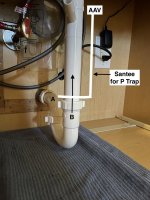
I have an old house with 50s plumbing. My problem is the single sink P trap sits less than a 1" off the cabinet base floor. The drain 2" sits low also (4" up the back wall). As a result it makes working on the drain difficult and to catch any water and trash in the trap. How can I raise the P trap higher without creating a S trap type of configuration? I don't think S traps are to code here.

You are using an out of date browser. It may not display this or other websites correctly.
You should upgrade or use an alternative browser.
You should upgrade or use an alternative browser.
Undersink plumbing
- Thread starter 1111ron
- Start date
Users who are viewing this thread
Total: 2 (members: 0, guests: 2)
If the pipe in the wall is vertical, you can move the santee up higher.
Or if you use a fitting to raise the arm on this side of the wall, you will need an AAV for the venting. Not code everywhere, but they do work.
Or if you use a fitting to raise the arm on this side of the wall, you will need an AAV for the venting. Not code everywhere, but they do work.
Sponsor
Paid Advertisement
You could, adding an AAV in the process. It's probably not worthwhile.
How about getting a small baking pan or cookie sheet, and beating down one end to slip under the the trap. Or how about putting a sheet of plastic underneath and drawing the corners up somehow.
Even slip a garbage bag with a drawstring under and up a tad.
A wet-dry vac can help empty out your catch device.
The pipe in the wall is Not vertical and behind that cabinet the wall is solid cinder block and stucco. Best I can tell is it turns to the left and then down. The vent stack to the roof is about 3 feet to the right and best guess is they put in a loop style vent within the wall.If the pipe in the wall is vertical, you can move the santee up higher.
Or if you use a fitting to raise the arm on this side of the wall, you will need an AAV for the venting. Not code everywhere, but they do work.
Not sure an AAV is code here but I could install that inside the cabinet. The marked up picture is crud but would this idea work? I'd turn fitting "A" 90 and attach it to a PVC stack against the back wall with a santee about 4" up and the AAV high in the cabinet. Then I could slide "B" the P trap up to connect to the Santee.
Attachments
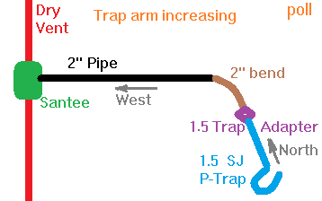
They were very unlikely to put a loop vent in the wall. Instead the trap arm would have continued horizontal until a vertical vent.
See https://terrylove.com/forums/index.php?threads/p-trap-install-stubs-out-too-low.68736/ for how you would handle what you are suggesting. But I think what you are suggesting is a fair amount of work for little advantage.
Seriously, a wet-dry vac could catch water as you pull the trap. I think those plastic nuts will lift up, and you will be able to slide the U of the trap sideways. Also, you could probably suck that trap dry with a wet-dry vac on the sink drain from above. And if it can't, a smaller tube pushed down the drain into the U could be sucked on by that vac. Even a vigorously-operated plunger may be able to remove most of the water in that trap before pulling the trap.
What is under that cloth? Maybe there is already a clearance slot, for all we know. ;-)
Also, what is that strip maybe 5 inches from the wall? Could it be there is a removable panel to make access easy?
If you are in Houston or San Antonio, an AAV is probably not allowed. But otherwise it probably is. But why? What you have is going to be functional. Pulling that trap should not be a regular occurrence.
Last edited:
Jeff H Young
In the Trades
how much is it worth to have this higher ? it doesn't look good under there now but adding an AAV and additional fittings under sink might not be a lot better . tearing open walls is a way to clean it up but wouldn't be my way , I'd leave it alone till I was remodeling or had a reason to do such work
Last edited by a moderator:
James23912
Member
It looks like there is a removable panel in there, the darker boards , one notched under the pipe going into the wall? There are screws in it, like it could be taken out.
how much is it worth to have this higher ? it doesn't look good under there now but adding an AAV and additional fittings under sink might not be a lot better . tearing open walls is a way to clean it up but wouldn't be my way , I'd leave it alone till I was remodeling or had a reason to do such work
I agree it's a fair amount of work for a small gain. I just happen to be working on this area due to a drain clog and a sink strainer leak. One day I will have to tear in to the wall and replace the galvanized pipe. I have that and about 6 feet under the concrete porch left to complete replacement of all buried cast and steel pipe drains.
They were very unlikely to put a loop vent in the wall. Instead the trap arm would have continued horizontal until a vertical vent.
See https://terrylove.com/forums/index.php?threads/p-trap-install-stubs-out-too-low.68736/ for how you would handle what you are suggesting. But I think what you are suggesting is a fair amount of work for little advantage.
Seriously, a wet-dry vac could catch water as you pull the trap. I think those plastic nuts will lift up, and you will be able to slide the U of the trap sideways. Also, you could probably suck that trap dry with a wet-dry vac on the sink drain from above. And if it can't, a smaller tube pushed down the drain into the U could be sucked on by that vac. Even a vigorously-operated plunger may be able to remove most of the water in that trap before pulling the trap.
What is under that cloth? Maybe there is already a clearance slot, for all we know. ;-)
Also, what is that strip maybe 5 inches from the wall? Could it be there is a removable panel to make access easy?
If you are in Houston or San Antonio, an AAV is probably not allowed. But otherwise it probably is. But why? What you have is going to be functional. Pulling that trap should not be a regular occurrence.
I agree not much advantage for the work needed. I guess I could cut a hole in the cabinet floor for the trap like in the other post but I'd rather not do that. Also agree several ways to dry out the trap as well so the current setup is not ideal but workable.
Nothing under the cloth except the floor. No hole in the cabinet floor. The strip you see is a removable panel I made to cover the unsightly wall behind it. No real gain is made with it removed. The cabinet guy just couldn't seem to measure drain and pipe cuts correctly and ended up with a large 10x12 cutout in the back cabinet wall.
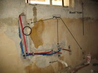
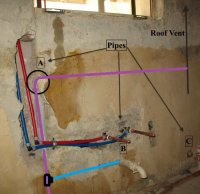
One thing I do know is the configuration is Not as drawn above! Some kinda version of a Loop vent is in that wall. Reasons are;
1. see attached pic of wall behind plumbing
2. notice pipe "A" to left of drain stubout "B" and a 90 at the top in the circled area
3. stubout "B" goes LEFT in the wall, not right, up or down. note: window is above stubout
4. pipe "C" has a cleanout plug and is directly in line with the vent pipe in the roof
5. Outside at the buried drain line there is a sweep tee roughly in line with pipe "A" and downstream there is another sweep tee roughly in line with pipe "C". Both of these pipes come from the direction of that wall.
additional info. There is NO other drains in the area of this. The washer is up stream about 30 feet and has its own vent pipe. The buried drain (2 inch) outside only services the washer and kitchen sink. The 2 inch drain ties into the main 4 inch drain 40 feet downstream
Attachments
Could be a 45, but more likely a 90. Attached sketch could explain things with a 90 at A. Vent pipes are allowed to go horizontal 6 inches above the flood level of the sink. It is compatible with you seeing the trap arm going left just inside the wall.2. notice pipe "A" to left of drain stubout "B" and a 90 at the top in the circled area
Yes, there are other posibilities.
Maybe an old-time studfinder with a magnet on a bearing could help you map the steel pipes.
Attachments
Could be a 45, but more likely a 90. Attached sketch could explain things with a 90 at A. Vent pipes are allowed to go horizontal 6 inches above the flood level of the sink. It is compatible with you seeing the trap arm going left just inside the wall.
Yes, there are other posibilities.
Maybe an old-time studfinder with a magnet on a bearing could help you map the steel pipes.
Old houses come with plenty of mysteries and surprises. Wished I had measured when it was torn up... but that does look to be just above the sink flood level. Guess I could try to map the pipes from the outside wall but that will need a strong magnet. Those walls are thick! Thanks
One last question. I found what had been a very slow leak at the metal 2" stubout to 1.5" tubular trap arm. Over time the calcium in the water pretty much sealed it so I didn't see it. Now that I have it off I need to reconnect it better. The contractor had slide the tubular pipe inside the 2" and used the standard plastic compression ring. The pipe face is pretty rough so the plastic ring was ate up and even a new one will probably never make a great seal.
I have heard of what is called a "marvel?" connector but can't find a 2" to 1.5 slip joint that is threaded at the hub side. All of them seem to be glue at hub end and for ABS pipe. I would like to make a good, secure leak free threaded connection on the stub side and have a proper clean mated slip joint on the other side. Do they make this and where can I find one?
I have heard of what is called a "marvel?" connector but can't find a 2" to 1.5 slip joint that is threaded at the hub side. All of them seem to be glue at hub end and for ABS pipe. I would like to make a good, secure leak free threaded connection on the stub side and have a proper clean mated slip joint on the other side. Do they make this and where can I find one?
Tuttles Revenge
In the Trades
- Messages
- 4,459
- Reaction score
- 1,575
- Points
- 113
Brass 1.5" Female IPS x 1.5" tubular trap adapter
https://www.ferguson.com/product/pr...d=&typeAheadType=product&typeAheadSearch=true
https://www.ferguson.com/product/pr...d=&typeAheadType=product&typeAheadSearch=true
wwhitney
In the Trades
Looking at the spec sheet, the main thing I see is that the female end has NPT threads, while the slip joint end has NPS threads.Brass 1.5" Female IPS x 1.5" tubular trap adapter
So does using a slip joint nut and washer directly on the NPT threads of a nipple generally work, but run the risk that the NPT threads may preclude tightening the slip joint nut sufficiently?
Cheers, Wayne
A 2 inch threaded pipe measures 2.375 OD, and a 1-1/2 inch pipe measures 1.90 OD.
Yes I understand pipe is generally measure by the ID so 2" PVC is 2 ID and 2.375 OD so how does this help me? Also I understand these undersink P trap kits thin pipe and the 1.5" size is actually the OD. Correct?
Yes I understand pipe is generally measure by the ID so 2" PVC is 2 ID and 2.375 OD so how does this help me? Also I understand these undersink P trap kits thin pipe and the 1.5" size is actually the OD. Correct?
Sounded like you were looking for a 2-inch FNPT trap adapter, and I suspected if you had found one, it would not fit.but can't find a 2" to 1.5 slip joint that is threaded at the hub side.
Sounded like you were looking for a 2-inch FNPT trap adapter, and I suspected if you had found one, it would not fit.
Ok. Please explain. Which end are you referring to? Sounds like your saying a 2" FNPT will not mate with a 2" MNPT fitting.
wwhitney
In the Trades
I think the issue is that nothing in your photos looks like 2" IPS, so when you say you have a metal 2" stubout, Reach4 is looking for confirmation that the stubout has 2.375" OD and not 1.9" OD.Ok. Please explain. Which end are you referring to? Sounds like your saying a 2" FNPT will not mate with a 2" MNPT fitting.
Cheers, Wayne
wwhitney
In the Trades
P.S. If you do have a 2" MIP stubout, then you could use a 2" x 1.5" bell reducer with a 1.5" MIP x 1.5" slip joint trap adapter, e.g.:
https://www.supplyhouse.com/Bluefin-BRC200-150-2-x-1-1-2-FIP-Brass-Coupling-Lead-Free
https://www.homedepot.com/p/Dearbor...Female-Copper-Sweat-Connection-1005/301811871
Cheers, Wayne
https://www.supplyhouse.com/Bluefin-BRC200-150-2-x-1-1-2-FIP-Brass-Coupling-Lead-Free
https://www.homedepot.com/p/Dearbor...Female-Copper-Sweat-Connection-1005/301811871
Cheers, Wayne
Similar threads
- Replies
- 26
- Views
- 2K
- Replies
- 1
- Views
- 373
- Replies
- 0
- Views
- 299
- Replies
- 0
- Views
- 654