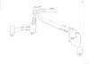
Please see attached well crafted artistic rendering.
I ran #12 wire from a 20A breaker to a junction box. From the junction box I created a pigtail and ran to the first GFCI outlet (Line) terminal. Also from the pigtail in the junction box I ran to a second GFCI outlet (Line). Then from the (Load) terminals on those GFCI's I ran to standard 15A receptacles.
When I switched on the breaker, the first GFCI clicked off and none of the other outlets including the other GFCI outlets were hot.
So I changed and wired so that the source went to the junction box. From the junction box I ran to only one GFCI (Line). From the (Load) of that GFCI I ran to the (Load) of a second GFCI.
With that set-up, the first GFCI worked correctly, but none of the other outlets were hot.
Shouldn't the wiring work as drawn?
Thanks for any assistance with figuring out this wiring. It seems straight forward enough, but obviously I'm mistaken.