Adding outlets and switch after GCFI - not working.

Users who are viewing this thread

Rmgolob

Member
Messages
92
Reaction score
3
Points
8
Location
Indiana
I HATE electricity.
Rant off....

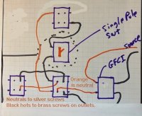
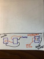
I have a GCFI and want to add 2 outlet receptacles and another outlet receptacle with a switch down stream.
Photo show the set up.
1 = GCFI
2 = New outlet #1
3 = New outlet #2
4 = Switch
5 = New outlet #3 for overhead light

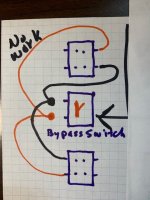
Second picture is how I wired and it does not work

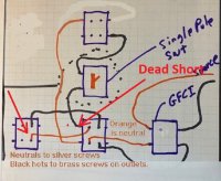
Third picture shoes 1 outlet after GCFI (as a test to see if I can go beyond the GCFI) - That works.

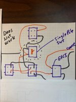
Forth picture shows the desired setup bypassing the switch (in case that was the problem) but that does not work either.

Suggestions please!!
 

Attachments

  • Photo.jpg
    Photo.jpg
    58 KB · Views: 231
  • Want this.jpg
    Want this.jpg
    58.7 KB · Views: 234
  • Works fine.jpg
    Works fine.jpg
    46.3 KB · Views: 235
  • bypass switch.jpg
    bypass switch.jpg
    62.8 KB · Views: 253
Last edited:

Reach4

Well-Known Member
Messages
38,899
Reaction score
4,436
Points
113
Location
IL
No photo included.

What kind of not-working? Not tripping during a test, or not supplying power downstream only, or not supplying power at all?

If you cascade the GFCI, you need to power the downstream from the load terminals, which are often covered when you buy the GFCI. The line terminals are always used, even for stand-alone.
 

Rmgolob

Member
Messages
92
Reaction score
3
Points
8
Location
Indiana
No photo included.

What kind of not-working? Not tripping during a test, or not supplying power downstream only, or not supplying power at all?

If you cascade the GFCI, you need to power the downstream from the load terminals, which are often covered when you buy the GFCI. The line terminals are always used, even for stand-alone.
Wow - What a quick response.
I accidentally posted prior to completing it.

Not working means it stays constantly tripped.
 

Reach4

Well-Known Member
Messages
38,899
Reaction score
4,436
Points
113
Location
IL
Not working means it stays constantly tripped.
It is important that the downstream hot and neutral come off of the load. Make sure that the neutrals of the downstream outlets are not joined with any other neutrals.

gfci-line-load-wiring-diagram.png


If you wired it right, and it trips with nothing plugged in, then there is probably a short of some sort downstream.

EDIT: I think you added the diagrams later. Does orange represent the white (neutral) wires that screw to the silver screws on the outlets? If yes, see attached:
 

Attachments

  • IMG_1.jpg
    IMG_1.jpg
    74.5 KB · Views: 240
Last edited:

Jadnashua

Retired Defense Industry Engineer xxx
Messages
32,770
Reaction score
1,190
Points
113
Location
New England
You cannot connect both of the red and black wires to the switch! The switch just breaks ONE of the connections, so depending on which color is which (hot/neutral), you'd only attach the HOT leads to the switch, and run the neutral straight to the lamp. So, come with the hot out of the GFCI to one pole of the switch, and then off of the other, run that to the hot lead of your lamp.

If you have both the red and black wires on the switch, when you close the switch, you're attaching hot directly to neutral...a classic short circuit. That MIGHT have fried the switch contacts, but the gfci should have tripped before that happened. You might have fried the GFCI as well.
 

Afjes

Member
Messages
98
Reaction score
37
Points
18
Location
Northeast PA
Reach4 gave you a good diagram to go by.

Looking at your diagram (attached) I noted that you are creating a dead short. If you are backstabbing the hot (backstabbing is bad to start with) behind the neutral that is causing your dead short. This should be tripping the circuit breaker. Move the back-stabbed hot from the neutral side, make a short jumper, wire nut together with the other hot and connect to the screw.

The receptacle to the left you are not completing the circuit and the way you have this wired will create a dead short also. Move the hot and neutral to either the upper or lower set of screws.

The other thing you need to look for is that the tab between the upper set of screws and lower set of screws is in place. Those are only removed in the case when you wire a split receptacle.

Note: If you are in fact back stabbing any connections this is not a good idea. They have been known to fail over time. Do not connect more than one wire to one screw. Use a small length of jumper wire and connect with wire nut and then connect the jumper to the screw on the receptacle.

You can insert wires into the back of the GFCI. This is not considered back-stabbing as the GFCI screw uses a pressure plate to secure the wire. This is different than back stabbing.

Also be very sure that your source power is connected to the "Line" side of your GFCI. Anything you want to protect gets connected to your "Load" side of the GFCI.
 

Attachments

  • IMG_1.jpg
    IMG_1.jpg
    105 KB · Views: 206

Rmgolob

Member
Messages
92
Reaction score
3
Points
8
Location
Indiana
It is important that the downstream hot and neutral come off of the load. Make sure that the neutrals of the downstream outlets are not joined with any other neutrals.

gfci-line-load-wiring-diagram.png


If you wired it right, and it trips with nothing plugged in, then there is probably a short of some sort downstream.

EDIT: I think you added the diagrams later. Does orange represent the white (neutral) wires that screw to the silver screws on the outlets? If yes, see attached:
Thank you!!
Despite my inaccurate drawing, this is what I did.
My BIG MISTAKE was wiring both Black and White to the switch (addressed in subsequent post by jadnashua.
Thank you
 

Rmgolob

Member
Messages
92
Reaction score
3
Points
8
Location
Indiana
You cannot connect both of the red and black wires to the switch! The switch just breaks ONE of the connections, so depending on which color is which (hot/neutral), you'd only attach the HOT leads to the switch, and run the neutral straight to the lamp. So, come with the hot out of the GFCI to one pole of the switch, and then off of the other, run that to the hot lead of your lamp.

If you have both the red and black wires on the switch, when you close the switch, you're attaching hot directly to neutral...a classic short circuit. That MIGHT have fried the switch contacts, but the gfci should have tripped before that happened. You might have fried the GFCI as well.
Thank you!
This was ultimately what I did wrong.
I was connecting Black and White to the switch.
All fixed now!!
 

Rmgolob

Member
Messages
92
Reaction score
3
Points
8
Location
Indiana
Reach4 gave you a good diagram to go by.

Looking at your diagram (attached) I noted that you are creating a dead short. If you are backstabbing the hot (backstabbing is bad to start with) behind the neutral that is causing your dead short. This should be tripping the circuit breaker. Move the back-stabbed hot from the neutral side, make a short jumper, wire nut together with the other hot and connect to the screw.

The receptacle to the left you are not completing the circuit and the way you have this wired will create a dead short also. Move the hot and neutral to either the upper or lower set of screws.

The other thing you need to look for is that the tab between the upper set of screws and lower set of screws is in place. Those are only removed in the case when you wire a split receptacle.

Note: If you are in fact back stabbing any connections this is not a good idea. They have been known to fail over time. Do not connect more than one wire to one screw. Use a small length of jumper wire and connect with wire nut and then connect the jumper to the screw on the receptacle.

You can insert wires into the back of the GFCI. This is not considered back-stabbing as the GFCI screw uses a pressure plate to secure the wire. This is different than back stabbing.

Also be very sure that your source power is connected to the "Line" side of your GFCI. Anything you want to protect gets connected to your "Load" side of the GFCI.
Thank you!
Unfortunately my drawing had "typos" in it.
I was actually wiring all Black to Gold and all White to Silver.
I did have the switch wired wrong. Corrected now.

To confirm when you state "back stabbing is bad" I take it you are referring to the push in connections on the backs of the outlets?
For example where I have 3 black wires attached to the outlet, I put 1 each on the 2 Gold screws and the third I pushed into the back.
You are saying this is not a good practice and I should jump 1 to another and only use the 2 screws?
 

Jadnashua

Retired Defense Industry Engineer xxx
Messages
32,770
Reaction score
1,190
Points
113
Location
New England
The spring mechanism that holds the wire in a back-stabbed device can wear out as opposed to a screw. It depends on how much current is carried through that connection. THe more current, the warmer it gets, and to an extreme, it can weaken the spring tension. THen, there's the situation where you didn't strip the wire properly, and it doesn't get the required grip, or too much is sticking out, potentially able to short on something...so, it may not be a great idea, but technically is okay. THe better way to connect is if the screw has a plate under it that compresses against the wire(s). Some of them will handle two wires, and then you don't have to fuss with making a loop around the screw. The devices rated for commercial tend to be better built and have those features. The home center ones at the price leader range, do not.
 

Afjes

Member
Messages
98
Reaction score
37
Points
18
Location
Northeast PA
As Jadnashua explained well the reason why "back stabbing" is not a good idea.

But again there is a difference between back stabbing and a pressure plate where you insert the wire in back of a plate and then tighten down the screw such as you will find on a GFCI. Using a pressure plate is fine.
 

Rmgolob

Member
Messages
92
Reaction score
3
Points
8
Location
Indiana
The spring mechanism that holds the wire in a back-stabbed device can wear out as opposed to a screw. It depends on how much current is carried through that connection. THe more current, the warmer it gets, and to an extreme, it can weaken the spring tension. THen, there's the situation where you didn't strip the wire properly, and it doesn't get the required grip, or too much is sticking out, potentially able to short on something...so, it may not be a great idea, but technically is okay. THe better way to connect is if the screw has a plate under it that compresses against the wire(s). Some of them will handle two wires, and then you don't have to fuss with making a loop around the screw. The devices rated for commercial tend to be better built and have those features. The home center ones at the price leader range, do not.
Great explanation - Thank you!
 

Rmgolob

Member
Messages
92
Reaction score
3
Points
8
Location
Indiana
As Jadnashua explained well the reason why "back stabbing" is not a good idea.

But again there is a difference between back stabbing and a pressure plate where you insert the wire in back of a plate and then tighten down the screw such as you will find on a GFCI. Using a pressure plate is fine.
Got ya - I appreciate it.
Thank you!
 
Top
Hey, wait a minute.

This is awkward, but...

It looks like you're using an ad blocker. We get it, but (1) terrylove.com can't live without ads, and (2) ad blockers can cause issues with videos and comments. If you'd like to support the site, please allow ads.

If any particular ad is your REASON for blocking ads, please let us know. We might be able to do something about it. Thanks.
I've Disabled AdBlock    No Thanks