Lightning damage to pump and casing?

Users who are viewing this thread

Reach4

Well-Known Member
Messages
38,893
Reaction score
4,436
Points
113
Location
IL
Assuming I do not install any check valves in the drop pipe, at the surface, or at the tank; is one still needed or recommended directly above the pump?
From what I have read, yes.
 

semipro

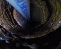
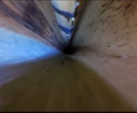
New Member
Messages
22
Reaction score
0
Points
1
Location
SW Virginia
I thought I'd report back that my son and I were able to replace the pump/motor. I thought I'd shared some notes/observations.
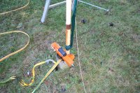
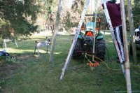
  1. We pulled the pipe/motor/pump using a 24 ft. tall homemade tripod constructed of soccer goal parts and steel pipe. A Warn winch mounted to the back of our tractor served as hoist. I invested in, and used, a Kwik Klamp, something I would strongly advise for the DIYer. I should have invested in an elevator clamp for our Sch. 80 1-1/4 PVC pipe. Using a piece of strap and a prusik knot worked ok but really consumed some time.
  2. The steel couplers between the PVC pipe sections were very corroded in some places. Some showed signs of perforation and leakage. Frankly, had the pump/motor not failed I wouldn't be surprised if it didn't fall to the bottom after a coupler broke. (would a safety cable help then?)
  3. One check valve was installed around 200 ft. below ground surface and was still working well. I did not reinstall this or any other check valve.
  4. The old Goulds unit shows no external sign of lightning damage. The production date was 1996. So it served well especially when you consider we sometimes use a well-source whole-house heat pump.
  5. The PVC pipe was in very good condition and quite flexible. We reinstalled it with stainless steel couplers and coated the threads with Rector-Seal with Teflon.
  6. We installed a 1.5 HP Franklin Super Stainless motor and Grundfos pump per recommendations found here. I used the supplied crimp-style splicers and soldered the connections also. Clear heat shrink was installed over each splicer.
  7. We did not install a safety cable/rope. Based on the condition of some of the pipe couplers maybe I should have?
  8. We did install some plastic pipe "standoffs" about every 100 ft.
  9. Electrical tape was used to secure the cable to the pipe once per pipe section. I was going to use stainless steel hose clamps but remembered reading that plastic pipe will stretch a bit. I didn't want the stretching pipe to put undue stress on the cable.
  10. I built a nice motor cooling shroud out of a Fernco flexible connector and some PVC pipe but found that I'd made it just a little too big in diameter to pass by the pitless adapter. I'd considered the casing and boring diameter but not the (darned) pitless adapter. I was trying to make the shroud as large a diameter as possible to minimize water flow restriction between the motor and shroud.
  11. I installed a new control box.
  12. We did not replace the cable and I question why that is so widely recommended. (Hope I don't find out the hard way). The cable looked new and looked to be of better quality than what I can buy now. With the price of copper and the issues involved with recycling coated wire I chose to reuse what we had.
  13. The cable in the well is 3+1 conductor that will be grounded at the top of the steel casing until I can run a ground to the power panel. (The existing wire from well to house is 2+1.
  14. We ran the pump for a while and purged the well a bit before dropping the assembly into the pitless adapter. I put a light coat of vaseline on the pitless o-ring because I didn't have a replacement figuring its easy enough to pull the pipe up again to replace the o-ring if needed. It does not appear to be leaking.
  15. Before work began I was able to inspect the casing from top to bottom using a video recording sports camera attached to a 300 ft. tape measure. I hanged a bright flashlight above the camera and both were focused downward. The imagery was actually quite good. I was able to tell that the casing was in good shape and that there were no leaks at the bottom of the casing where it was sealed to the bedrock.
Many thanks to all those here that offered advice. As I've reported, I relied heavily on it.
 
Last edited:

Reach4

Well-Known Member
Messages
38,893
Reaction score
4,436
Points
113
Location
IL
I put a light coat of vaseline on the pitless o-ring because I didn't have a replacement figuring its easy enough to pull the pipe up again to replace the o-ring if needed.
That is the one thing that is specifically not recommended. You should have used silicone grease or release compound. The problem with vaseline is that it can swell the O-ring. So have a replacement O-ring available if you pull the pump again.

I think you probably would want to tape the wires more times, and leave a tad of slack between taped places.

Pictures would be interesting.

Well done.
 
Last edited:

semipro

New Member
Messages
22
Reaction score
0
Points
1
Location
SW Virginia
I knew going in that Vaseline, being petroleum-based, might swell the o-ring. I actually have silicone grease on hand for plumbing. Given that the o-ring was old and stiff I figured a little swelling could only help it seal. Had I know the right sized o-ring going in I would have bought one. Trouble is I couldn't find out what size to buy not knowing the make of the pitless adapter.

Thanks for the feedback.
 

Valveman

Cary Austin
Staff member
Messages
14,633
Reaction score
1,304
Points
113
Location
Lubbock, Texas
Website
cyclestopvalves.com
Good job. Couple of things you could have done a little differently. Using standoffs for the wire is not needed, taping is all that is required. And the smaller the diameter of the shroud the better it cools the motor. A 1/4" gap between the shroud and motor will let 60 GPM pass easily.

I use a 1" pitless and bush up to 1 1/4" pipe so a 4" shroud will fit past it in 5" casing.
 

semipro

New Member
Messages
22
Reaction score
0
Points
1
Location
SW Virginia
2.5 years on since we installed the new pump/motor and all is well. I thought I'd share a few photos for grins.
1. Downhole camera borehole view
2. downhole camera casing view
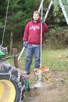
3. My son while we're testing the flow
4. The downpipe clamp
5. Winch mounted to the tractor and tripod

Well borehole.JPG Well Casing.JPG IMG_3038.jpg IMG_3028.jpg IMG_3034.jpg
 
Top
Hey, wait a minute.

This is awkward, but...

It looks like you're using an ad blocker. We get it, but (1) terrylove.com can't live without ads, and (2) ad blockers can cause issues with videos and comments. If you'd like to support the site, please allow ads.

If any particular ad is your REASON for blocking ads, please let us know. We might be able to do something about it. Thanks.
I've Disabled AdBlock    No Thanks