Grundfos went out, replacing with Goulds +CSV

Users who are viewing this thread

blaise_am

New Member
Messages
2
Reaction score
0
Points
1
Location
Texas
Hi All,

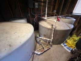
Moved to a property about a year ago, we have a well that pumps to 2 storage tanks and a MQ3-45 pumps to 2 separate houses. The Grundfos went out this past weekend and I want to use this opportunity to make the water run smoother (pretty bad pressure drop in the first 2-3 seconds with the Grundfos and no pressure tank).

Parts purchased:
- Goulds J10S (going to be used at 115V)
- PK1A Pside-Kick Pressure Tank Kit w/10 gallon tank
- 1.25" check valve

Attached is an image of the current setup. Not 100% sure about some of the connections, but want make sure the parts above are sufficient/recommended for the goal.

All tips/advice/criticism is welcome and encouraged. Thanks!
 

Attachments

  • IMG_9130.jpg
    IMG_9130.jpg
    82 KB · Views: 55

Valveman

Cary Austin
Staff member
Messages
14,633
Reaction score
1,304
Points
113
Location
Lubbock, Texas
Website
cyclestopvalves.com
Sounds like a good plan. I would ditch the plastic check valves and use one metal, spring loaded, poppet style check valve, preferably on the suction side of the pump.
Jet pump from cistern.jpg
 

John Gayewski

In the Trades
Messages
4,363
Reaction score
1,348
Points
113
Location
Iowa
Sounds like a good plan. I would ditch the plastic check valves and use one metal, spring loaded, poppet style check valve, preferably on the suction side of the pump.
View attachment 95142
I've seen this before. I've wondered about the check valve being on the suction side of a pump. Most pump applications (hyronics, plumbing, and industrial ) that I'm familiar with preach about having the check valve (if any) on the discharge side of a pump so stuck checkor broken check can't ruin a pump. But most well pump diagrams I've looked at show it on the pump's inlet. How come?I'm just curious.
 

Valveman

Cary Austin
Staff member
Messages
14,633
Reaction score
1,304
Points
113
Location
Lubbock, Texas
Website
cyclestopvalves.com
I've seen this before. I've wondered about the check valve being on the suction side of a pump. Most pump applications (hyronics, plumbing, and industrial ) that I'm familiar with preach about having the check valve (if any) on the discharge side of a pump so stuck checkor broken check can't ruin a pump. But most well pump diagrams I've looked at show it on the pump's inlet. How come?I'm just curious.
A stuck or broken check can ruin a pump no matter which side it is on. I like the check valve on the suction side so the pump starts under pressure. It is much easier for a pump to start with pressure against it than without. Check valve on the discharge side means the pump is at zero pressure when it comes on.
 

John Gayewski

In the Trades
Messages
4,363
Reaction score
1,348
Points
113
Location
Iowa
I guess the common thinking is an instantly ruined pump (with the check failing or breaking on the inlet) is worse then a pump that is being prematurely worn with the check on the outlet that fails in a detrimental way.

But almost any diagram I've seen with well pumps show them on the inlet side. I was just curious where this comes from. The industrial pumps I'm talking about are tens of thousands of dollars or more that might make a difference. The hydronic pumps are pretty weak and that might make a difference in common practice also.
 
Top
Hey, wait a minute.

This is awkward, but...

It looks like you're using an ad blocker. We get it, but (1) terrylove.com can't live without ads, and (2) ad blockers can cause issues with videos and comments. If you'd like to support the site, please allow ads.

If any particular ad is your REASON for blocking ads, please let us know. We might be able to do something about it. Thanks.
I've Disabled AdBlock    No Thanks