All good stuff. Yeah you will need to just drill a small hole in the pump check valve as there is too much elevation to make a bleeder orifice of any brand work. You can also add more than one air vent at the top if needed. An additional continuous acting air vent after the pressure tank should prevent any air from getting to the house. Instead of an air vent you can also just use a check valve on a tee that will let air in up top, but will close and not let anything out when the pump starts.
You are using an out of date browser. It may not display this or other websites correctly.
You should upgrade or use an alternative browser.
You should upgrade or use an alternative browser.
Drainback system - air-over-water or diaphragm pressure tank?
- Thread starter magicdog
- Start date
Users who are viewing this thread
Total: 2 (members: 0, guests: 2)
Greenmonster123
Active Member
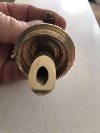
I installed a valve in the casing with a rod up to just under the cap. This way I’m the warmer months I can close the valve and not have to worry about any air getting in.All good stuff. Yeah you will need to just drill a small hole in the pump check valve as there is too much elevation to make a bleeder orifice of any brand work. You can also add more than one air vent at the top if needed. An additional continuous acting air vent after the pressure tank should prevent any air from getting to the house. Instead of an air vent you can also just use a check valve on a tee that will let air in up top, but will close and not let anything out when the pump starts.
Sponsor
Paid Advertisement
Nice idea. Going to rig up a rod as a linkage?
This might be a good time to replace the o-ring, or at least figure out what you would need.
 www.maassmidwest.com
Robert Dicken invented one of the first pitless adapters, and in 1941 founded Dicken Manufacturing to produce this innovative product for the water well industry. Dicken Manufacturing consisted of a machining facility and brass foundry. In addition to the pitless adapter, this Arcadia, Ohio, plant also manufactured well caps, tank tees, and cast brass insert fittings. Winrock Enterprises acquired Dicken Manufacturing in 1975, and in 1984 merged it with Midwest Well Supply.
www.maassmidwest.com
Robert Dicken invented one of the first pitless adapters, and in 1941 founded Dicken Manufacturing to produce this innovative product for the water well industry. Dicken Manufacturing consisted of a machining facility and brass foundry. In addition to the pitless adapter, this Arcadia, Ohio, plant also manufactured well caps, tank tees, and cast brass insert fittings. Winrock Enterprises acquired Dicken Manufacturing in 1975, and in 1984 merged it with Midwest Well Supply.
This might be a good time to replace the o-ring, or at least figure out what you would need.
About Maass Midwest, Inc. | Manufacturers of Quality Water Well Accessories
Greenmonster123
Active Member
Yes it has a rod on it I put it on right after picture was taken. It has been in the well for 2 years now.Nice idea. Going to rig up a rod as a linkage?
This might be a good time to replace the o-ring, or at least figure out what you would need.
Robert Dicken invented one of the first pitless adapters, and in 1941 founded Dicken Manufacturing to produce this innovative product for the water well industry. Dicken Manufacturing consisted of a machining facility and brass foundry. In addition to the pitless adapter, this Arcadia, Ohio, plant also manufactured well caps, tank tees, and cast brass insert fittings. Winrock Enterprises acquired Dicken Manufacturing in 1975, and in 1984 merged it with Midwest Well Supply.About Maass Midwest, Inc. | Manufacturers of Quality Water Well Accessories
What do you think about that 5 gpm claim, and how would that relate to the 5 to 10 psi claim? It is not making sense to me. Pumping into an open pipe over an atmospheric tank would seem different from pumping thru a check valve into a pressure tank.I re-read the OP where he said the cottage is 65 feet up a very steep hill so the head pressure will be too high for the Flowmatic Model 70 automatic drain valve to open unless several are placed about 20 - 25 feet apart along the run. The Flowmatic Model 70 automatic drain valve is spring loaded and it takes a 5 GPM flow of water to overcome the spring and close the valve. That means that most of the air will get purged by the drain valves. It also means that water will spurt out the valves.
LLigetfa
DIYer, not in the trades
The friction created by flowing 5 GPM around the spring-loaded valve is what is needed to overcome the spring force that opens and holds open the drain valve.What do you think about that 5 gpm claim, and how would that relate to the 5 to 10 psi claim? It is not making sense to me. Pumping into an open pipe over an atmospheric tank would seem different from pumping thru a check valve into a pressure tank.
Are you thinking that the Model 70 would add about 5 to 10 psi of pressure drop to the flowing water?The friction created by flowing 5 GPM around the spring-loaded valve is what is needed to overcome the spring force that opens and holds open the drain valve.
LLigetfa
DIYer, not in the trades
No, it would not affect the pressure when closed.Are you thinking that the Model 70 would add about 5 to 10 psi of pressure drop to the flowing water?
What do you think the reference to 5 -10 psi refers to?No, it would not affect the pressure when closed.
Flow has nothing to do with it. Pressure over 10 PSI will push it closed.
LLigetfa
DIYer, not in the trades
Flow has nothing to do with it.
I expect you are right, and https://www.flomatic.com/assets/pdf_files/oem/16016.pdf is not right.Flow has nothing to do with it. Pressure over 10 PSI will push it closed.
It would be nice for some drainback systems if there was a device that opened to the air when the flow was low or stopped, but closed the drain when the water was flowing up from the pump.
Does anyone know of a valve similar to the attached and linked below? This would allow the OP to have this three way valve just above the sub. pump. when water pumps up the secondary output is closed off. When the pump stops the valve closes, opening the secondary output and allowing the drain back to flow out the secondary. This would eliminate the need for the wye with reducer or drilling a hole in the line and thereby eliminate pressure/water loss when the pump is pumping.Reading the more recent posts I'm realizing the Flowmatic 70 valve I intended to get would probably be subjected to more than the 10 PSI required to open.
I'm not sure if it makes sense to install several of the Flowmatic valves along the run up the hill as they will be subjected to freezing conditions. The Flowmatic websites specifies installation below the frost line.
I think the simplest solution, as shown on the Cottage Water Supply website, is to install a simple wye fitting with reducer. Or even simpler drill a hole.
Seems less elegant and it would rob the system of some efficiency but it would likely still work. Even a 1/8" hole would be more than fine.
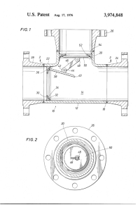
US3974848A - Three pot two way check valve - Google Patents
A three port, two way check valve is disclosed. It is made of a standard tee and standard flanges attached thereto, typically in conformance with API standards. A flat disc is inserted in one of the openings, the disc incorporating an inernal circular valve seat and a hinged valve member which...
patents.google.com
Attachments
Looks like it would work well, but I have never seen one. A lot of things get patented but never produced. Just because it is a good idea doesn't mean there is enough demand for the product to start production. Especially with a new idea, as it takes many years for people to start using something new.
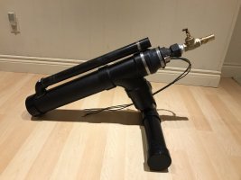
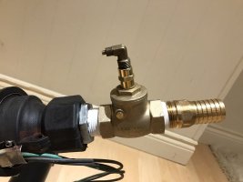
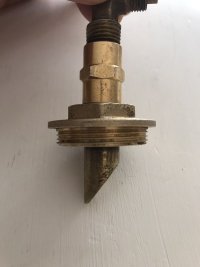
I was searching for a valve with that function, and had no luck. Being a tinkerer at heart, I built what I hope is a functional equivalent out of a standard swing check valve. The threaded 'cap' on the branch side of the check was drilled and tapped 1/4" NPT. A short brass nipple was threaded in from the inside of the cap. The nipple was carefully marked and trimmed on an angle so the flapper in the check properly closes off the nipple when swung open by pump flow. When pump stops, the flapper swings back to rest position, opening the nipple port. I'll see if I can get some pictures to upload. This hasn't been tested in the lake yet, but we hope to do that this fall. First pic is the submersible pump stand that will sit on the lake bottom. Pump pulls water past the motor via the 1-1/2" ABS intake that's open at the top of the assembly.Does anyone know of a valve similar to the attached and linked below? This would allow the OP to have this three way valve just above the sub. pump. when water pumps up the secondary output is closed off. When the pump stops the valve closes, opening the secondary output and allowing the drain back to flow out the secondary. This would eliminate the need for the wye with reducer or drilling a hole in the line and thereby eliminate pressure/water loss when the pump is pumping.
US3974848A - Three pot two way check valve - Google Patents
A three port, two way check valve is disclosed. It is made of a standard tee and standard flanges attached thereto, typically in conformance with API standards. A flat disc is inserted in one of the openings, the disc incorporating an inernal circular valve seat and a hinged valve member which...patents.google.com
Attachments
Looks like it will work. That is some fine tinkering tight there. Lol! But I believe it pretty much negates the function of the check valve. Might as well just drill a hole in any check flapper and let it bleed back through the pump slowly.
Yeah, the pump already has an integral check on the outlet, so the check function of the swing check isn't really necessary I don't think. I keep hearing others state that draining back through the pump is a bad idea, as it can spin backwards, potentially damaging the pump. Not sure if this is simply the action of spinning in reverse, or if the damage occurs if the motor is re-started whilst spinning backwards. Any thoughts on this?
Yeah, the pump already has an integral check on the outlet, so the check function of the swing check isn't really necessary I don't think. I keep hearing others state that draining back through the pump is a bad idea, as it can spin backwards, potentially damaging the pump. Not sure if this is simply the action of spinning in reverse, or if the damage occurs if the motor is re-started whilst spinning backwards. Any thoughts on this?
Both. It hurts the thrust bearing to spin either direction at less than 50% speed, and if it tries to start while spinning backwards it will break the shaft or coupling. But drilling a 1/4" hole in the check valve on the pump will keep it from spinning backwards. They actually make drain back check valves that way for large irrigation pumps.
Similar threads
- Replies
- 5
- Views
- 562
- Replies
- 15
- Views
- 1K
- Replies
- 1
- Views
- 481
- Replies
- 8
- Views
- 1K
- Replies
- 10
- Views
- 780