A Buffer tank issue?

Users who are viewing this thread

Alan Dunn

New Member
Messages
25
Reaction score
0
Points
1
Location
Canada
IBC SL 10-85 G3 boiler with DHW connection on the left and zone connection on the right plus a 27g buffer tank.

For my own reference, I strapped two separate Azel temp sensors, one on zone supply pipe and one on return, just two feet away from the boiler as depicted in Drawing_1.

Some of the zone piping in the drawing is behind the boiler and DHW tank and not into just to clarify.

I understand this IBC will see better efficiency with coolest possible return water temp (rwt) and ODR is hooked up/operational.

My issue is that while boiler is giving me the proper delta T on the swt vs swt as shown in the Azel gauge as in Azel_gauge_2. (132.8 swt/115.7 rwt in this instance), but, by the time zone return water mixes with the buffer tank near the boiler inlet, you can see rwt elevates to 131F from the boiler as in Boiler_Reading_3.

15F warmer.

Does it mean this buffer tank mixes up too much warmer water with the rwt there on the bottom? Is there any way I can help with that?

Any input is appreciated.
 

Attachments

  • Drawing_1.pdf
    88.3 KB · Views: 235
  • Azel_gauge_2.jpg
    Azel_gauge_2.jpg
    21.8 KB · Views: 216
  • Boiler_Reading_3.jpg
    Boiler_Reading_3.jpg
    31.6 KB · Views: 230

Dana

In the trades
Messages
7,889
Reaction score
509
Points
113
Location
01609
It's drawn rather strangely, but it appears that the buffer tank is set up to be a hydraulic separator where the boiler flow loop intersects with the radiation flow loop, which will always decrease the delta-T on the boiler, increasing the entering water temp at the boiler, lowering the temperature of the water going out to radiation.

In your case the primary and secondary loops connect at the external tees- think of the top 5th and bottom 5th of the tank in this picture as really fat tees- it's the same flow pattern:

sht0515sieg7.jpg


While hydraulic separation is almost always required for high-head water tube heat exchanger boilers, most low head fire-tube heat exchanger boilers (like the SL 10-85) can be set up to pump direct on a single loop (no primary/secondary), in which case putting the buffer tank in series with boiler would make the entering water temp at the boiler the same as the return water temp from radiation. But you'll have to do the math to make sure under all conditions the flow through the boiler is still in the right range, not over pumped, not under-pumped.
 

Alan Dunn

New Member
Messages
25
Reaction score
0
Points
1
Location
Canada
Very much appreciate it Dana!

I'm attaching an actual setup photo here.

Please elaborate what you meant by "putting the buffer tank in series with boiler" to ensure the cool temp return zone water coming back to the IBC without being diluted by the buffer.

Right now, the supply water temperature seems fine (ie temp leaving the supply outlet on the boiler is consistent with what it is near the zone valves) as evidenced in my last two attachments.

It is just boiler is not seeing the cool return zone water when it arrives at the boiler inlet. It is substantially higher. View attachment 56669
 

Dana

In the trades
Messages
7,889
Reaction score
509
Points
113
Location
01609
Please elaborate what you meant by "putting the buffer tank in series with boiler" to ensure the cool temp return zone water coming back to the IBC without being diluted by the buffer.

I guess I need an editor, eh? :) (It's sometimes hard to believe 'merican dialect is my first language!) What that says isn't exactly what I meant- only sort-of.

When plumbed primary/secondary, if the flow through the boiler loop is higher than the flow through the radiation the temp at the bottom of the buffer tank is higher than the return water temp since boiler output is being drawn down into the tank by the primary pump flow. If the systgem is plumbed as one loop and pumped direct that can't happen- there isn't a dilution of the return water with boiler output water.

With the current plumbing & pumping configuration you may be able to get there by backing off the flow on the primary (boiler) loop. Be sure that the delta-T on the boiler doesn't go too high (I'm not sure what that boiler's max spec is, but most can take up to 50F delta-T at the boiler). At some low flow there is also some risk of flash-boil "kettling" on the heat exchanger, where the micro-boil isn't being moved by fast enough to keep it from making bigger bubbles that collapse audibly as contact with the heat exchanger is broken. If it begins to sizzle & pop when throttling back the flow is definitely too low.
 

Dana

In the trades
Messages
7,889
Reaction score
509
Points
113
Location
01609
I just looked up the spec.

*Max delta-T= 40F (not the 50F guesstimate in response #4)

*Minimum flow= 2 gpm

*Maximum flow= 14 gpm

With a max flow of 14 gpm it's almost certain you'd be able to pump direct, no primary/secondary, as long as all zones are running at least 2gpm.
 

Alan Dunn

New Member
Messages
25
Reaction score
0
Points
1
Location
Canada
Dana, do you suggest to turn off that Grundfos 15-58 pump near the boiler return at the bottom near the buffer and just let the Alpha (which is currently at AutoAdapt mode) does all the pumping? The Grundfos is at the lowest speed 1 at the moment.
 

Dana

In the trades
Messages
7,889
Reaction score
509
Points
113
Location
01609
Dana, do you suggest to turn off that Grundfos 15-58 pump near the boiler return at the bottom near the buffer and just let the Alpha (which is currently at AutoAdapt mode) does all the pumping? The Grundfos is at the lowest speed 1 at the moment.

Without the 15-58 on the primary loop the flow through the boiler would drop to near-zero with just the Alpha running, unless it was replumbed, with the return from radiation entering ONLY the buffer (and not the boiler), and the output of the buffer feeding ONLY the return side of the boiler.

59896341-05.jpg


Take a look at the boiler head loss chart on page 2 of the short spec. The head loss of the tank and nearby plumbing are essentially zero, assuming the tank and boiler are next to one another, so the boiler's head is essentially the total head for that loop. At 6 gpm the head loss on the boiler is 2.5', at 8 gpm the head loss is 3'. Looking at the pump curves for the 15-58, even when it's set to 1 it's probably pumping 7+ gpm through the primary loop. That's fine for the boiler- it won't hurt it, but it's probably higher than the radiation flow, and higher than it needs to be even when all zones are calling for heat.

Re-plumbing it with the buffer tank in series rather than paralleled-up with two pumps, two flow rates would pump 100% of the radiation flow through the boiler, but it can probably take it. Without more information on your radiation and design heat load I can't really make that call with certainty, but you can probably figure it out.

Short of re-plumbing, throttling back the primary flow to 2-4 gpm with a ball-valve on the primary loop (giving the 15-58 more head to pump against) may be the simplest way to bring the entering water temp at the boiler down into the condensing range without completely re-designing the system. I suspect nobody really did the math on this before it was installed- a great many installers just guess, throw in a multi-speed primary pump big enough to almost hit the max flow rate for the boiler, then fiddle with the settings to where it sorta-kinda works. It may be worth sketching out the math to see if it really needs to be set up primary/secondary, and if it still does, a smart pump on the primary loop would give you better options for dialing in performance than the 15-58, if the ball-valve throttle approach seems too kludgey.
 

Alan Dunn

New Member
Messages
25
Reaction score
0
Points
1
Location
Canada
Thank you Dana. Let me chew on it a bit to see if I get it. Greatly appreciate it!

Here's the actual photo I meant to attach earlier

Actual_Setup_Photo1.jpg
 

Dana

In the trades
Messages
7,889
Reaction score
509
Points
113
Location
01609
If instead of the 15-58, a smart pump set to constant flow of the boiler's minimum 3 gpm (=~1500lbs/hr) would almost surely cover the space heating load At the boiler's max 40F delta-T that would be 40F x 1500lbs/hr= 60,000 BTU/hr. If that's not enough, 4 gpm at a delta-T of 40 F would hit (or exceed, at non-condensing temps) the maximum output numbers for that boiler.

For a better guesstimate of what makes sense, where are you located (for design temperature/weather data purposes), and how big is the house (for a shot the likely heat load at your local outside design temp.)
 

Alan Dunn

New Member
Messages
25
Reaction score
0
Points
1
Location
Canada
System.jpg
If instead of the 15-58, a smart pump set to constant flow of the boiler's minimum 3 gpm (=~1500lbs/hr) would almost surely cover the space heating load At the boiler's max 40F delta-T that would be 40F x 1500lbs/hr= 60,000 BTU/hr. If that's not enough, 4 gpm at a delta-T of 40 F would hit (or exceed, at non-condensing temps) the maximum output numbers for that boiler.

For a better guesstimate of what makes sense, where are you located (for design temperature/weather data purposes), and how big is the house (for a shot the likely heat load at your local outside design temp.)

We live not too far north of Seattle in a 2,700 sq.ft. house built in 1997 with 7 zones (I guess that's the reason for the buffer, except it kills the condensing return water temp at the current setup).

Avg. outside winter temp : high=47F ; low=38 F. Design temp that I can research is "Heating 99% Dry Bulb = 25F".

The type of the emitter is attached in the photo here.

Many thanks
System.jpg
 

Dana

In the trades
Messages
7,889
Reaction score
509
Points
113
Location
01609
A design temp of 25F is credible. Vancouver's 99% outside design temp is +24F/-4C. A reasonably air tight 2x6/R19 type house with clear-glass (no low-E) double-panes that size with NO foundation insulaion should come in at under 35,000 BTU/hr @ -4C outside/20C inside, and could easily be under 27,000 BTU/hr if tighter than average, with low-E glass and an insulated foundation.

The emitters in the picture look like dangling, un-installed PEX. Does the radiant floor have metal heat spreaders to help get the heat out of the PEX and into the subfloor, convective vanes on suspended tubing, or bare tubing or ...??

How many square feet of active radiant floor area (zone by zone)?

index.php
 

Alan Dunn

New Member
Messages
25
Reaction score
0
Points
1
Location
Canada
View attachment 56739 View attachment 56740 View attachment 56741 View attachment 56739
A design temp of 25F is credible. Vancouver's 99% outside design temp is +24F/-4C. A reasonably air tight 2x6/R19 type house with clear-glass (no low-E) double-panes that size with NO foundation insulaion should come in at under 35,000 BTU/hr @ -4C outside/20C inside, and could easily be under 27,000 BTU/hr if tighter than average, with low-E glass and an insulated foundation.

The emitters in the picture look like dangling, un-installed PEX. Does the radiant floor have metal heat spreaders to help get the heat out of the PEX and into the subfloor, convective vanes on suspended tubing, or bare tubing or ...??

How many square feet of active radiant floor area (zone by zone)?
We actually did a heatloss calculation (attached) if that helps.

The piping is not dangling in our place. It is just an online pic that I used. I attached a pic here on the aluminum convection plate with insulation that is more application to our setting here.

I also found a diagram with reference specifically on buffer setup in the IBC manual that I attached here.

I wonder if one pump location makes any difference (IBC has two pumps on the supply whereas we have one on supply/retrun): View attachment 56739 View attachment 56740 View attachment 56741
View attachment 56739
 

Alan Dunn

New Member
Messages
25
Reaction score
0
Points
1
Location
Canada
Attachment resent:
IBC_Manual.png
HeatLossCalculation.jpg
 

Attachments

  • ultra_fin plate.jpg
    ultra_fin plate.jpg
    25.5 KB · Views: 204
  • ibc with buffer manual.pdf
    133 KB · Views: 277

Dana

In the trades
Messages
7,889
Reaction score
509
Points
113
Location
01609
I'll take a deeper dive on this later, but at first blush, to start with a heat load of 44,000 BTU/hr @ 32F is not a credible number for a 2700' house built in the 1990s, unless it has so much glass it looks like a fish bowl or terrarium (?).

For reference, I live in a 2400' + 1600' of insulated basement 2x4 framed house built in the 1920s (insulated later), with mostly original windows + clear storms, only a couple of low-E windows. The true heat loss at my house doesn't hit 44,000 BTU/hr until it's about -8F/-22C outside.

If you have a heating history on the place, run a fuel-use based load calculation (wintertime gas bills only) to get a better handle on it.

Looking at your near-boiler plumbing there is enough twists & turns between the buffer and boiler to add a bit more pumping head, so you may actually "only" be running 5-6 gpm, not 7+. But a low-low delta-T at the boiler is an indication that whatever that rate is, it's a bit too high.
 

Alan Dunn

New Member
Messages
25
Reaction score
0
Points
1
Location
Canada
ok Greatly appreciate all your help, Dana. We do have two vaulted ceilings. Not sure if it makes any difference. But will try the fuel-use based calculation after I dig out all the gas bills which also included the DHW usage though. Does it matter?

One twist here. This afternoon, I just took another look at the 15-58 pump near the return and noticed it was set at high speed #3 which, in turn, I immediately turned it down to low speed #1.

It's a bit cold outside at 45F now this evening. One zone (650 sf ft) is on right now. I have been setting the boiler delta T at 20F. And indeed the supply/return near the manifold according to the Azel gauge is showing at 133F/112F. Quite dead on.

But IBC sensor tells me supply/return spread is 136F/130F. 6F difference. Better than 2F before when this Gundfo 15-58 was set at speed #3.

Dana, you're right on that flow rate is at 6.93 gpm now whereas I noticed it was at more than 13, 15gpm when this 15-58 pump set at high speed#3.

But still trying to fight to achieve the 112F return to the boiler or thereabout. I am determined to get that with all the wonderful help from Dana. Many thanks.
 

Dana

In the trades
Messages
7,889
Reaction score
509
Points
113
Location
01609
ok Greatly appreciate all your help, Dana. We do have two vaulted ceilings. Not sure if it makes any difference. But will try the fuel-use based calculation after I dig out all the gas bills which also included the DHW usage though. Does it matter?

When using wintertime-only data the DHW is a smaller fraction of the total gas use, and it's more or less being offset by the solar gain. In spring/fall the solar gain error can easily outstrip the DHW error or conversely- depending on how much glass, how much hot water use, etc.

One twist here. This afternoon, I just took another look at the 15-58 pump near the return and noticed it was set at high speed #3 which, in turn, I immediately turned it down to low speed #1.

It's a bit cold outside at 45F now this evening. One zone (650 sf ft) is on right now. I have been setting the boiler delta T at 20F. And indeed the supply/return near the manifold according to the Azel gauge is showing at 133F/112F. Quite dead on.

The delta-T at the manifold is controlled by the Alpha, not the boiler settings, since its on the secondary loop, not the primary. To measure the primary loop directly the sensors have to be right at the boiler, before the tees at the buffer tank.

The delta-T at the boiler can't hit 20F unless the output temp is set much higher. A flow of 7 gpm is 3500 lbs/hr x 20F would be 70,000 BTU/hr, which would be pretty much the maximum non-condensing firing rate output of that boiler, which you neither need nor want.

But IBC sensor tells me supply/return spread is 136F/130F. 6F difference. Better than 2F before when this Gundfo 15-58 was set at speed #3.

Dana, you're right on that flow rate is at 6.93 gpm now whereas I noticed it was at more than 13, 15gpm when this 15-58 pump set at high speed#3.

But still trying to fight to achieve the 112F return to the boiler or thereabout. I am determined to get that with all the wonderful help from Dana. Many thanks.

So it sounds like the Alpha is doing the right thing, delivering a 20F delta-T on the radiation, which is fine. It would be fine to reduce that to 15F or 10F if it improves the entering water temp at the boiler. Increasing the flow on the radiation to reduce it's delta-T will reduce supply temp a few degrees, and increase the return water temp. But if the supply temp is currently 132F, return 112F (20F delta-T), reducing the supply to 127F and increasing the return to 117F (a 10F delta-T) the entering water temp of the boiler is likely to drop, since there's a greater volume of return water mixing in with the boiler output at the buffer tank/tees.

At 3500 lbs/hr and a delta-T of 6F is ( 6F x 3500lbs/hr=) 21,000 BTU/hr, which is also fine- not the lowest firing rate, but in the lower third. The 21K probably much higher than your actual immediate heat load, but with thermal mass of the tank it's probably not short-cycling. Time the burns as well as the off intervals to the nearest 5 seconds, and report back.

At an entering water temp (EWT) of 130F and firing in the lower third of it's range you're looking at about 88-89% raw combustion efficiency out of the boiler. If you can knock back the EWT another 5F-8F by a combination of boosting the flow on the radiation &/or throttling back the flow on the primary to something like 3 gpm it'll be cruising into the condensing range.

Most buffer tanks have options for separate ports for the boiler & radiation rather than external tees. In the picture it looks like you have two capped-off ports(?). Plumbing the secondary loop/manifolds to the separate ports from the boiler connections like this would allow the buffer tank to function better as a hydraulic separator, not merely a buffer. Ideally the boiler return water connection would be at the same level or lower than the manifold return, and the manifold supply port would be above the boiler supply connection, but even if that's not possible it would still work better than external tees.
 

Alan Dunn

New Member
Messages
25
Reaction score
0
Points
1
Location
Canada
Interesting. Never knew by narrowing secondary's delta-T will help lowering EWT. I will see how I work the Alpha 2 15-55 to increase the radiation flow. Right now, it is on AutoAdapt mode. I will try Constant Pressure mode later and play with the three speeds.
alphapump.jpg

It is colder this evening at 38F outside. At this moment,
Secondary SWT/EWT= 149F/114F
Primary SWT/EWT= 153F/149F
Boiler Target Temp=148F
Boiler Heating Output=10MBtu
 

Dana

In the trades
Messages
7,889
Reaction score
509
Points
113
Location
01609
I'm not sure why you need a target temp of 148F when it's only 38F outside. Have you done any fine tuning of the outdoor reset curve?

The whole curve can probably be shifted down by 15-20F and it may still keep up, given that the reported firing rate is running 10,000 BTU/hr out (~11,500 BTU/hr in), very close to the boiler's MBH minimum firing rate. Keep adjusting the temperatures downward until one or another zone just doesn't keep up overnight. I've never set up the reset curve on that series boiler, but it can't be all that complicated (can it?). If you need help figuring out the reset curve, post a link to the appropriate manual and I'll take a look.

The boiler's 4F delta-T @ 7 gpm would indicate an output rate of 14,000 BTU/hr, input of about 16K, but that could easily just be due to the rounding error on temperature sensor.
 

Alan Dunn

New Member
Messages
25
Reaction score
0
Points
1
Location
Canada
I'm not sure why you need a target temp of 148F when it's only 38F outside. Have you done any fine tuning of the outdoor reset curve?

The whole curve can probably be shifted down by 15-20F and it may still keep up, given that the reported firing rate is running 10,000 BTU/hr out (~11,500 BTU/hr in), very close to the boiler's MBH minimum firing rate. Keep adjusting the temperatures downward until one or another zone just doesn't keep up overnight. I've never set up the reset curve on that series boiler, but it can't be all that complicated (can it?). If you need help figuring out the reset curve, post a link to the appropriate manual and I'll take a look.

The boiler's 4F delta-T @ 7 gpm would indicate an output rate of 14,000 BTU/hr, input of about 16K, but that could easily just be due to the rounding error on temperature sensor.

I always thought the type of setup and emitter that we have are not identical to concrete slab installation. In fact, the design temp on our emitter type is calling for 180F. We didn't max to that 180F.

Our Design Supply Temp set in the boiler is 165F at Design Outdoor Temp of 25F. Min Supply Temp is 115F.

Here's the screen shot:

Load 1_home heating setting.jpg


I also attach a link on the curve starting Page#15 of this PDF manual.
http://www.ibcboiler.com/support/TI...screen_Controller_Manual_English_R5_email.pdf
 

Dana

In the trades
Messages
7,889
Reaction score
509
Points
113
Location
01609
The Ultra-Fin installation brochure indicates that it puts out about 7 BTU/hr per square foot into a 70F room at a water temp of 100F, and about 27 BTU/hr per square foot at a water temp of 150F, which is a LOT!

It's important to get a better handle on the actual zone by zone load numbers and the square footage of the radiant floor supplying that heat to get a good estimate of what the water temperatures need to be. As I indicated in response #14, the 44K heat load @ 32F is simply not a credible number, and if the curves were set up using that load calculation the water temperatures can be lower, and I suspect it's MUCH lower (which is why you never need 180F water, since you never need 44K of output out of the radiation.)

In the absence of better load numbers it's still possible to find out what water temperatures are actually needed empirically, by lowering the water temperatures to the point where the zone thermostats are almost never being satisfied, but the room temps aren't actually losing ground.

On p16 of the boiler manual they state:

Where outdoor reset is applied without the indoor sensor feedback option, some manual adjustment may be required to achieve the desired comfort level.

Do you have the indoor sensor option?

I assume you have the outdoor sensor installed, so that the boiler actually knows the outdoor temp?

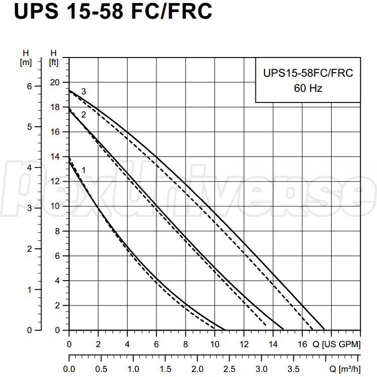
With the thermal mass of a buffer tank in the system you probably don't have to be concerned about setting temperature minimums to avoid short-cycling issues, but with fin-tube baseboard in some zones you probably want to set the minimum at about 110-115F, since the output of fin-tube below that temperature is very non-linear (but the Ultra-Fin should still do fine at very low water temps.)

I suspect your whole-house load is about 30-35K @ +25F, about 3/4 of the 44K that the radiation emits at 180F (per your sheet.) If that WAG is correct, all else being equal (no under or over-radiated zones) you should be able to heat the house to 70F indoors with ~155F water when it's 25F outside (which delivers ~30 BTU/hr per square foot out of the radiant, ~400 BTU/hr per running foot out of the fin tube), and the reset curve would drop the supply temp to 115F when it's 55F or so outside. But for tighter, better insulated houses it could easily be as low as 140F @ 25F outside and still work.

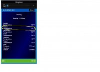
Looking your screen shot of programming options, leave the 115F minimum temp alone for now (110F would probably be OK too) but set the Design Supply Temperature to 155F, see it it still keeps up overnight. If it does, drop Design Supply Temperature to 145F and see if it keeps up overnight. If it does, cut it another 5F to 140F @ +25F outdoors.

Keep going 5F at a time on successive days until you find the water temperature at which one or more zones lose ground overnight, always below the thermostat's setpoint. When that Design Supply Temperature temperature is found, raise it back up 5F for a day to verify that it still keeps up, then start backing off just degree at a time. With a week's worth of cool weather you can probably get it dialed pretty closely, but may still need to tweak it up again a degree at a time if it starts losing ground at outdoor temps below 30F (or below 25F.)

In IBC's terminology the "supply differential" is the range of temperature swing around the target temperature that the boiler allows before firing or re-starting the boiler. eg, when the curve's target temp is 133F and the differential is set to 20F it will turn off the burner when when the system temp rises to where it hits 143F even at minimum fire, and won't refire until it drops to 123F. As long as it's not short-cycling (probably won't with a buffer that size) setting it to 10F would probably keep it in the condensing zone more of the time. (TBD.)

Time the actual burns, not just the calls for heat from the thermostats. With a boiler like this burns as short as 3 minutes are just fine, as long as the burns per hour aren't more than 5. I suspect the thermal mass of the buffer is enough to ensure burns longer than that that no matter how little heat is being emitted by the zone radiation, even with a 10F Supply Differential.
 
Top
Hey, wait a minute.

This is awkward, but...

It looks like you're using an ad blocker. We get it, but (1) terrylove.com can't live without ads, and (2) ad blockers can cause issues with videos and comments. If you'd like to support the site, please allow ads.

If any particular ad is your REASON for blocking ads, please let us know. We might be able to do something about it. Thanks.
I've Disabled AdBlock    No Thanks