Advice on well house plumbing

Users who are viewing this thread

freemarmoset

New Member
Messages
21
Reaction score
0
Points
1
Location
Washington
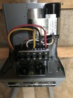
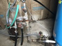
Upcoming plans to add a house filter and water softener to our current system along with a pressure switch that needs replacement due to age/failure, and discovery that there's currently no pressure relief valve, has led me to decide to replumb all the connections in our well house.

Picture is attached. It's currently mostly old galvanized (1 1/4") from the pump discharge to the pressure tank with a PVC T with a redundant pressure switch and no pressure relief valve. And then galvanized going down to 1" and then 3/4" feeding 3 PE supply lines leading out of the well house (1" supplies our home, 3/4" supplies barn 1, 3/4" supplies barn 2 and a couple of hydrants).

I want to add a proper brass T with a single pressure switch and relief valve and replace all the old galvanized. My first question is what material would you recommend? Copper, PVC? If I went with copper, would I need a dielectric at the pump discharge? I have a quote from a well contractor from about a year ago that specced out replacing the feed from the pump to the tank and the tank to the supply lines with 1" I.D stainless Flex pipe. That's certainly appealing to a DIYer in that it would save time cutting and gluing or soldering, and seems reasonable, but is that a terrible idea?

Second, would you keep the line between the pump and the tank 1 1/4" like it currently is, or just drop to 1" at the pump discharge. I've heard that's common and certainly what the old quote I have was suggesting, but would love to hear thoughts on that as well.

Thanks in advance!
 

Attachments

  • IMG_6625.JPG
    IMG_6625.JPG
    98.7 KB · Views: 486

Reach4

Well-Known Member
Messages
38,899
Reaction score
4,436
Points
113
Location
IL
I want to add a proper brass T with a single pressure switch and relief valve and replace all the old galvanized. My first question is what material would you recommend? Copper, PVC? If I went with copper, would I need a dielectric at the pump discharge?
PVC and copper are good. Even 1 inch PEX may be good. How big is your pressure tank, and what is the minimum time that the pump runs. Rule of thumb is that the pressure tank should take at least a minute to fill. If your pump delivers 10 gpm, then a 44 gallon tank would be appropriate. Tanks bigger than 32 gallon typically have a 1.25 connection. I have not heard about a need for dielectric isolation.

So 1 inch PVC and even PEX would be sufficient for 10 gpm from the pump.

I have a quote from a well contractor from about a year ago that specced out replacing the feed from the pump to the tank and the tank to the supply lines with 1" I.D stainless Flex pipe.
Not all flex pipes are similar. The braided stainless wraps a braid around a rubber or plastic tube. Falcon Mega-Flow corrugated stainless connector lines would be a good choice probably.

If I redo my pressure tank connection, I intend to use 1 inch PEX with F1960 expansion connectors. FYI, 1 inch PEX is not very flexible. More flexible than PVC, but not to where flexible is an appropriate word for shorter distance. One flexibility you do get, is the ability to slowly rotate at an elbow. The inside of the 1 inch pex will get discolored by iron. So I might seek out blue 1 inch PEX A.

Another type of piping that could be useful is SIDR polyethylene, as you have going into your concrete. SIDR piping is larger ID than a similar nominal size of PEX. Putting the pipe on the barbs is harder with SIDR.

Speaking of well houses, if you are running new wire, it is sometimes a good idea to put a subpanel for the electric. Then you can have utility outlets, heater, lights, outside outlets for the party stuff, or whatever down the line.
 
Last edited:

freemarmoset

New Member
Messages
21
Reaction score
0
Points
1
Location
Washington
How big is your pressure tank, and what is the minimum time that the pump runs. Rule of thumb is that the pressure tank should take at least a minute to fill. If your pump delivers 10 gpm, then a 44 gallon tank would be appropriate. Tanks bigger than 32 gallon typically have a 1.25 connection. I have not heard about a need for dielectric isolation.

So 1 inch PVC and even PEX would be sufficient for 10 gpm from the pump.

The pressure tank is 81 gallons and the well inspection and flow test from when we moved to the property a few years ago showed 17gpm direct from the discharge when unrestricted. I haven't paid close attention to the running time but I don't feel like it's ever been less than a minute. So would that mean sticking with 1.25 between the pump and tank would be better?

Not all flex pipes are similar. The braided stainless wraps a braid around a rubber or plastic tube. Falcon Mega-Flow corrugated stainless connector lines would be a good choice probably.

If I redo my pressure tank connection, I intend to use 1 inch PEX with F1960 expansion connectors. FYI, 1 inch PEX is not very flexible. More flexible than PVC, but not to where flexible is an appropriate word for shorter distance. One flexibility you do get, is the ability to slowly rotate at an elbow. The inside of the 1 inch pex will get discolored by iron. So I might seek out blue 1 inch PEX A.

Another type of piping that could be useful is SIDR polyethylene, as you have going into your concrete. SIDR piping is larger ID than a similar nominal size of PEX. Putting the pipe on the barbs is harder with SIDR.

Thanks for that info. The corrugated lines do look like a good option if I'm looking for maximum flexibility. I did consider polyethylene, and thought dealing with a bunch of barbs on a lot of short connections might be more trouble than it was worth, but maybe it wouldn't be. Pex is really appealing now that you mention it. I probably didn't think of it just because I've never worked with it and it would be an investment in some new tools. Would you say the pex is more/less/similarly flexible to the SIDR polyethylene?

With the number of projects I've got backed up on this farm, I'm really just going for speed ease of installation...without doing something stupid or taking shortcuts that I'd just regret in a few years. :)

Speaking of well houses, if you are running new wire, it is sometimes a good idea to put a subpanel for the electric. Then you can have utility outlets, heater, lights, outside outlets for the party stuff, or whatever down the line.

And speaking of those projects, it's funny you should mention this. I'm not running new wire right now, but there's some question as to the whether the full run to the well house in an appropriate gauge for pump, so a new line and a sub panel is on the docket for the near future.

Thanks for the reply!
 

Reach4

Well-Known Member
Messages
38,899
Reaction score
4,436
Points
113
Location
IL
The pressure tank is 81 gallons and the well inspection and flow test from when we moved to the property a few years ago showed 17gpm direct from the discharge when unrestricted. I haven't paid close attention to the running time but I don't feel like it's ever been less than a minute. So would that mean sticking with 1.25 between the pump and tank would be better?
I think so. Note in PVC pipe, some is pressure rated, some is DWV rated, and some is dual-rated. Same with fittings. You need pressure rated.
 

WY_WaterWellGuy

New Member
Messages
11
Reaction score
4
Points
3
Location
Wyoming
For the sake of simplicity I would probably just duplicate your current setup except replace the galvanized with threaded brass fittings. You can check your local plumbing codes to see if a dielectric union is required but you would probably be fine without one. Would also recommend replacing the gate valves with regular full port ball valves but that’s just personal preference. Would also suggest keeping it 1.25” all the way to the tank. Copper or threaded stainless fittings would work fine also. Glued PVC would probably be fine too, I just don’t like the way it looks, especially when it looks like someone spilled the whole bottle of glue on the pipes

Also would highly suggest adding a liquid filled pressure gauge somewhere near the tank/switch as it looks like there isn’t one? Bizarre
 
Last edited:

Reach4

Well-Known Member
Messages
38,899
Reaction score
4,436
Points
113
Location
IL
I think so. Note in PVC pipe, some is pressure rated, some is DWV rated, and some is dual-rated. Same with fittings. You need pressure rated.

One inch PVC or SIDR maybe, but for pex, 1-1/4 would be better. Click Inbox, above.
 

Skoronesa

Member
Messages
35
Reaction score
21
Points
8
Location
East Bumfuk, Mississippi
We use the thicker black polypropylene pipe, essentially it's pex, with brass insert fittings and two hose clamps. That goes from well head to tank tee which is threaded brass. Stainless fittings have gotten competitive with brass but some guys say they have issues with the fittings leaking if they aren't cranked tight.

The one major suggestion I have is that you use good hangers and if you use metal pipe you should wrap the pipe with some electrical tape before putting the hanger on. The pipe will condensate and it will corrode the pipe a lot, the tape helps prevent this and it's cheap/easy. I always chuckle when I walk into a basement and I see length of copper cold pipe with all the milfords rotted off at the crimp. Condensation and galvanic reaction between the metals.
 

Valveman

Cary Austin
Staff member
Messages
14,633
Reaction score
1,304
Points
113
Location
Lubbock, Texas
Website
cyclestopvalves.com
You are doing good to figure the best way to plumb everything. You should take a little time to figure out that a 81 gallon tank only holds 20 gallons of water, and will cause lots of pump cycling. With the number of different water requirements around a farm, using a Cycle Stop Valve to turn your pump into a variable flow pump that will match any amount of water you use without cycling the pump will make the pump last longer and deliver strong constant pressure to any place you use water. Installing a PK1A kit with a 4.5 or 10 gallon tank will also take up much less room and be much easier to plumb.

All you need is one of these.
pk1a-md.jpg


This is how it works.

And this is a before and after picture from someone who has done this before.
Before PK1A.jpg

After PK1A.jpg

And here is what they said about it.
"Before the CSV, watering my 2500sq ft lawn was cycling my well 20 times per hour for the 4 hrs twice a week. Now it comes on once and stays on at around 56psi at the 7gpm the sprinklers draw. Also dropped my wattage on the pump from 2800w down to 1900w at that flow rate. Another big plus is zero water hammer now, no more shaking the 275' of drop pipe when pump shuts off! Win win situation all around. Great device!"
 

freemarmoset

New Member
Messages
21
Reaction score
0
Points
1
Location
Washington
Thanks so much for all the advice everyone. After thinking through the options I think I'll probably using PVC to replace the the steel.

Also would highly suggest adding a liquid filled pressure gauge somewhere near the tank/switch as it looks like there isn’t one? Bizarre

There is one (broken) on the back side (pressure switch is blocking it in the picture), which I'll be replacing. Thought it was more bizarre to have 2 pressure switches and no pressure relief. Also, agree on the full port ball valves.

Installing a PK1A kit with a 4.5 or 10 gallon tank will also take up much less room and be much easier to plumb.

Cary, after reading more, I'm seriously considering the CSV. It's appealing to get as much life as possible out of an already aging pump, constant pressure will make orchard irrigation more accurate, etc. I do have a couple of questions though. I first noticed the switch failure when it failed to shut off the pump and tripped the pressure relief on my water heater (yep no relief currently by the tank). That tells me that had to have built up pressure to above 150psi to do that right? I read responses to other folks questions/concerns about back pressure on the pump. I think that all makes sense to me, but I still wonder about the right size valve for my pump. Is the 1A with a 1gpm minimum flow sufficient for the 3hp pump which clearly built up more than 150psi when the switch failed? Still learning a lot here and this is where I start to get confused. I mean based on the flow test that was done the most the pump would produce with no restriction right out of the 1.25 outlet was 17.1gpm. Is it possible to build up too much pressure behind the valve?
 

Valveman

Cary Austin
Staff member
Messages
14,633
Reaction score
1,304
Points
113
Location
Lubbock, Texas
Website
cyclestopvalves.com
A pump that produces 17 GPM from a wide open pipe is usually a 10 GPM series pump. If you have a 10 GPM series in 3HP, that pump can build as much as 476 PSI. That pump is designed to pump from a well that is 800'-900' deep. If your water level is more shallow than that, the pump is just way too large for the well depth. That pump will work great with a CSV1A if the water level in the well is 700' or deeper. If the water level is less than 700', you just have way too large a pump for that well. The fact that is popped off the relief valve on the water heater at 150 PSI is not good, but the CSV could still control it if the pressure is below 175 PSI.

With two of the CSV1A valves in series we can handle as much as 275 PSI coming in to the CSV. The first CSV takes the 275 and brings it down to 150 PSI. The second CSV1A would take the 150 PSI down to the 50 PSI you need. This would work with a 3HP, 10 GPM series pump as long as the water level was 460' or deeper.

Having a pump designed for 800'-900' in a much more shallow well is one of the hardest things for a CSV. However, the CSV is not the problem, rather the pump being way oversized is.
 

freemarmoset

New Member
Messages
21
Reaction score
0
Points
1
Location
Washington
A pump that produces 17 GPM from a wide open pipe is usually a 10 GPM series pump. If you have a 10 GPM series in 3HP, that pump can build as much as 476 PSI. That pump is designed to pump from a well that is 800'-900' deep. If your water level is more shallow than that, the pump is just way too large for the well depth. That pump will work great with a CSV1A if the water level in the well is 700' or deeper. If the water level is less than 700', you just have way too large a pump for that well. The fact that is popped off the relief valve on the water heater at 150 PSI is not good, but the CSV could still control it if the pressure is below 175 PSI.

With two of the CSV1A valves in series we can handle as much as 275 PSI coming in to the CSV. The first CSV takes the 275 and brings it down to 150 PSI. The second CSV1A would take the 150 PSI down to the 50 PSI you need. This would work with a 3HP, 10 GPM series pump as long as the water level was 460' or deeper.

Having a pump designed for 800'-900' in a much more shallow well is one of the hardest things for a CSV. However, the CSV is not the problem, rather the pump being way oversized is.

Ugh. Well that sounds like if that's the case, short of replacing the pump, my best bet is to remain with the same system I have now. Maybe I can track down who originally installed the pump and find out exactly what it is. I'm not optimistic though. Previous homeowners probably had it done quite a while ago. Is there any other way to check that short of pulling the pump up.
 

freemarmoset

New Member
Messages
21
Reaction score
0
Points
1
Location
Washington
This is the flow test I was mentioning. I think I read it right, and that would make the water level a little over 200 ft. I'm having a hard time getting my head around if someone actually installed a pump THAT overpowered for a well.
 

Attachments

  • flow.jpg
    flow.jpg
    89.2 KB · Views: 227

Reach4

Well-Known Member
Messages
38,899
Reaction score
4,436
Points
113
Location
IL
This is the flow test I was mentioning. I think I read it right, and that would make the water level a little over 200 ft. I'm having a hard time getting my head around if someone actually installed a pump THAT overpowered for a well.
It could have been that that test was done with a different pump for testing the well itself, rather than the one that was left installed. I don't know the probability of that, but it sometimes happens. You may have info that it was the same pump.
 

freemarmoset

New Member
Messages
21
Reaction score
0
Points
1
Location
Washington
It could have been that that test was done with a different pump for testing the well itself, rather than the one that was left installed. I don't know the probability of that, but it sometimes happens. You may have info that it was the same pump.

This was from the test that was done about 2.5 years ago when we moved to the property, and I was there when they did it, so I do know it was this pump.

So going back to the drawing board do you think there any further testing I could/should do to get any better idea of what the pump might be to determine an appropriate (and safe) setup? With any luck, the folks who put their sticker on the control box have some records and will be able to get back to me, but I'm not holding my breath. As with many systems on this property, it may be a mystery. All my assumptions have been based on the control box and the flow report. And this setup "working" for the past 10, 20, who knows how many years.
 

Attachments

  • IMG_6621.JPG
    IMG_6621.JPG
    73.6 KB · Views: 227

Valveman

Cary Austin
Staff member
Messages
14,633
Reaction score
1,304
Points
113
Location
Lubbock, Texas
Website
cyclestopvalves.com
Well if that is the pump still in the well, it does make me think it is a 10 GPM, 3HP. A 2HP or smaller would produce less than 15 GPM at those depths. Your static water level should be 216', and it looks like it only pulled down to 250' after many hours of pumping. That would tell me the pump should be set at 300+ feet and would be lifting from a max of 250'. A 1HP or at most a 1.5Hp in 10 GPM series would have been sufficient.

Yes if it is a 3HP, 10 GPM with a static level of 216', then staying with the old pressure tank system is your best option. Just need a large enough tank or tanks to get 2 minutes of run time. One minute is really not enough with a 3HP pump.

When you have a pump that is made to work up to 1,100' and the water level is only 250', there is too much back pressure (386 PSI) to use a Cycle Stop Valve. If you had a 1Hp or 1.5HP the CSV would be a no brainer. A CSV can work with a pump like that if the water level was at 800' or so.
 

Valveman

Cary Austin
Staff member
Messages
14,633
Reaction score
1,304
Points
113
Location
Lubbock, Texas
Website
cyclestopvalves.com
This was from the test that was done about 2.5 years ago when we moved to the property, and I was there when they did it, so I do know it was this pump.

So going back to the drawing board do you think there any further testing I could/should do to get any better idea of what the pump might be to determine an appropriate (and safe) setup? With any luck, the folks who put their sticker on the control box have some records and will be able to get back to me, but I'm not holding my breath. As with many systems on this property, it may be a mystery. All my assumptions have been based on the control box and the flow report. And this setup "working" for the past 10, 20, who knows how many years.

Yep. Control box says 3HP.

Should be a date code on the control box, but I don't see it? If it has lasted 10-20 years you are not cycling it enough to hurt anything. It is all in how you use water. Lightly used pumps will last a long time. Pumps that run 24/7/365 will also last a long time, But pumps that cycle on and off 50 or 100 times a day don't last long. Regular cycling for house use only when using a large tank is not going to hurt the pump. Running 12-15 GPM for long periods of time will not hurt the pump because it will run continuously. Running less than 12 GPM for any length of time will cycle the pump to death.
 
Last edited:
Top
Hey, wait a minute.

This is awkward, but...

It looks like you're using an ad blocker. We get it, but (1) terrylove.com can't live without ads, and (2) ad blockers can cause issues with videos and comments. If you'd like to support the site, please allow ads.

If any particular ad is your REASON for blocking ads, please let us know. We might be able to do something about it. Thanks.
I've Disabled AdBlock    No Thanks