Moving water tanks up the hill for more pressure - Need advice on piping

Users who are viewing this thread

Blue Oak

Member
Messages
36
Reaction score
9
Points
8
Location
Morgan Hill
As I hand dig the final connections, I'm wondering how I will be able to monitor the water level in the tanks. My existing steel tank has a float ball inside with a very thick fishing line type plastic string going up and over a wheel/pulley and down the outside of the tank. At the end of the string is a good sized deep sea fishing weight that I can see from a distance. As the water goes down in the tank, the weight on the outside rides up. It's typically completely full, but one time it was low and was the result of a drought not giving me enough water to keep up with my landscape watering, and the other was when a wire became loose on the "3 way switch" type thing that controls the electricity to the pump.

These poly tanks don't have a provision for the pully, and I'm wondering what others do to monitor water level from a distance?
 

Jadnashua

Retired Defense Industry Engineer xxx
Messages
32,770
Reaction score
1,190
Points
113
Location
New England
Will you have power up at the tanks? There are some wireless sensors, but to be viable, you'd want power versus batteries running them. Wireless would also need a clear line of sight, and that may be a bigger thing. The plastic tank might support installation of a sight tube up the outside, and you might be able to put a dark colored float in that would give you an indication of the level, assuming you could see it. Do you have to worry about freezing?

WHen I lived in the middle east (Jordan and Kuwait), we lived with a water storage tank on the roof, and one floor down was all of the water tower pressure we had. It was livable, but not great. I'm guessing maybe 10' max at the shower head, so barely 4 pounds. Static water pressure change is about 0.43#/foot. Dynamic pressure drop comes from friction, so the larger the pipe diameter to slow the flow in the pipe at the outlet is the biggest help, and the number of changes of direction is your bigger contributor to pressure loss along the way. A bigger pipe can help keep pressure loss through friction down.
 

Blue Oak

Member
Messages
36
Reaction score
9
Points
8
Location
Morgan Hill
Will you have power up at the tanks? There are some wireless sensors, but to be viable, you'd want power versus batteries running them. Wireless would also need a clear line of sight, and that may be a bigger thing. The plastic tank might support installation of a sight tube up the outside, and you might be able to put a dark colored float in that would give you an indication of the level, assuming you could see it. Do you have to worry about freezing?

WHen I lived in the middle east (Jordan and Kuwait), we lived with a water storage tank on the roof, and one floor down was all of the water tower pressure we had. It was livable, but not great. I'm guessing maybe 10' max at the shower head, so barely 4 pounds. Static water pressure change is about 0.43#/foot. Dynamic pressure drop comes from friction, so the larger the pipe diameter to slow the flow in the pipe at the outlet is the biggest help, and the number of changes of direction is your bigger contributor to pressure loss along the way. A bigger pipe can help keep pressure loss through friction down.

I will not have power at the tanks. I could pull a little haha romex but there is no power where I'm starting the trench. It does freeze and I want it to be good down to about 20*. The tanks do have a 2" NPT fitting near the top of each one. I'm leaning towards making a mechanical device much like my existing float and weight setup. I have a couple of machinist friends who could probably come up with something of a pully that fits in one of the ports. I was planning on the well switch wire going in one and water from the well going in the other, but the wire could be a simple drill through the poly to install.
 

Blue Oak

Member
Messages
36
Reaction score
9
Points
8
Location
Morgan Hill
Success! I have 35 PSI with the shower running at the upper/main house. Success criteria was greater than 30 PSI.

The water pump does not kick on anymore, since it doesn't drop down below 30 PSI. I'll be removing the pumps. The lower house I haven't tested, but I'm assuming it has 7 or 8 more PSI due to additional difference between the elevation of the house and tank. Both houses should enjoy some improvement with the removal of the pumps that are idle but inline.

I ended up buying a tank level gauge from rainwaterequipment.com but I haven't received that yet.

I'll post pictures after finishing up the float switch and level gauge. Running the float switch cable through about 170 feet of conduit was a breeze. I got some heavy duty construction string and tied a bit of plastic bag to the end. The cordless shop vac pulled it through the conduit in about 30 seconds, and gravity helped out a great deal when pulling the cable through.
 

Blue Oak

Member
Messages
36
Reaction score
9
Points
8
Location
Morgan Hill
I had a minor setback and a mild panic today when I couldn't get my well pump to activate. There were two electrical conduits going up the side of the old steel tank. I decided that I'd check the newer looking conduit first, and found two live wires as verified by my "Greenie." Score, no need to check the other junction box- plus the ladder is pretty sketch and I'm working next to trenches I've dug, etc. I carefully cut the PVC about 6 feet from where I want to mount my junction box and glued up some conduit popping up where I wanted it.

I left the two wires apart for a few hours, but nothing pumped so I figured it's connected to a switch that creates a circuit when it calls for water. I twisted the wires together, and didn't get a response either. It was a few hours later I remembered the second conduit going up the side of the tank. Back on the sketchy old aluminum extension ladder, the one with the end literally ripped off it leaving gigantic burrs ready to cut my throat, I carefully made the ascent. It was at the top of the tank I saw a little junction box I'd seen sometime before. I saw an obviously mechanical, rusty switch popping up out of that little junction like box and gave it a poke or two. Solid, effective actuation. I pushed it in and held it down- pushing the old, half deflated bulb of a float under water and gave it a listen. A couple seconds go by then the glorious sound of water pumping into the tank!

It won't be much trouble to extend the wires from the working float switch conduit over to where my junction box is planned, but what were those other two wires, and why do they light up the greenie? I can understand going with the working switch, but what they **** are the other two single strands of black wire that have an accompanying green ground wire? I really have no idea where they go, and at which house. I've been here almost 5 years and have had no problems with the well side of the water system, so I'm just now getting acquainted with it. I do know they don't match any of the wires at the relay assy in the water closet of my guest house. BTW, the relay has leads coming off, 4 or 5 inches long and just cut off and left attached there at some point. That's the kind of electrical expertise and discipline I find all over both houses. :eek:
 

Blue Oak

Member
Messages
36
Reaction score
9
Points
8
Location
Morgan Hill
If the existing steel tank is going to be used for fire reserve you may consider having it painted inside with a product such as to extend the tanks longivity

http://wildpowersports.com/steel-it...HadjPsv-R15FDE1MGCtoMm_m94VS5ODxoCOakQAvD_BwE

Thanks. I think after 50+ years the rust on the inside will preclude most coatings. I know for a fact there's at least one hole in the bottom of the tank, as I plugged it with a sheetmetal screw. I'm going to see how long it lasts, and at the point of failure look into repairing it. For now it's holding water.
 

Blue Oak

Member
Messages
36
Reaction score
9
Points
8
Location
Morgan Hill
Did I miss it, how does these new tanks get water? Nice planning and execution!

These new tanks are fed from the existing well that's been in place for over 50 years. I think it's about 400 feet underground, then about 400 more feet of pipe to get it around the houses and up the hill to the new location. So far the well has been able to fill them just fine. I'm getting 5 to 8 minutes of pumping from the well with a rest of about 13 mins to allow the water to re-accumulate at the bottom of the well.

I Tee'd off the pipe from the well at the existing steel tank and put a ball valve there. Since the new tanks are much higher in elevation, the single ball valve is effective for directing water. The only caveat is the float switch has to be calling for water, so sometimes I have to use a bunch of water in the yard to get the float switch to activate.

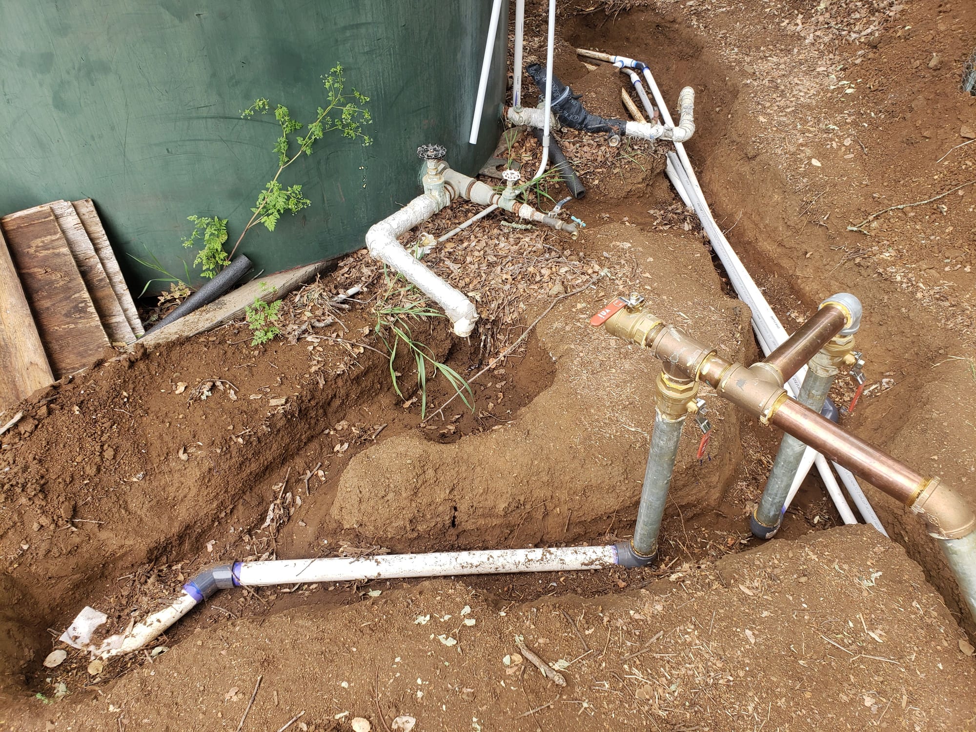
Below is a picture of how I tied the new piping together. The main manifold is front and center. This is the 2" pipe coming down from the new tanks, and it splits off to the two house supply lines. At the top/right there are three pipes visible in the trench. One is the 1" fill line going up the hill to the tanks, another is the 2" supply line going to the guest house, and the third is a 1" conduit with the wrong float switch wiring.

Thanks for the compliment. I've spent a long time thinking about how to do it and it's paid off.

80-well_connections_f39e4f662206a93d9769389dccba0267648a7d72.jpg
 

Blue Oak

Member
Messages
36
Reaction score
9
Points
8
Location
Morgan Hill
The old steel tank has some dog legs left on it that used to feed the houses. I need to clean that up. The large feed in the foreground will have a ball valve and an NH thread for a fire hose.
 

Valveman

Cary Austin
Staff member
Messages
14,633
Reaction score
1,304
Points
113
Location
Lubbock, Texas
Website
cyclestopvalves.com
Good job! It is good that you have a hill tall enough to make this work, most people do not. However, it looks like a lot of work and expense that a simple pump in the cistern would eliminate. Really not saving any energy as it cost as much to pump water to the top of the hill as it would to just boost the pressure.

You can fix a hole in a metal tank by whittling a dry wooden peg and driving it into the hole. The dry wood gets wet and swells to make a tight fit and will last a long time. I have seen old galvanized pressure tanks that look like a porcupine they have so many wooden pegs driven in the side. Lol!
 

WorthFlorida

Clinical Trail 5th session completed 4/24/24.
Messages
5,763
Solutions
1
Reaction score
998
Points
113
Location
Orlando, Florida
Good job! It is good that you have a hill tall enough to make this work, most people do not. However, it looks like a lot of work and expense that a simple pump in the cistern would eliminate. Really not saving any energy as it cost as much to pump water to the top of the hill as it would to just boost the pressure.

I had the same thoughts Cary, but then Blue Oak mentions the well doesn't seem to be able to provide a continuous supply of water and must allow time, during pumping, for the well to recover. Would a CSV be beneficial with a well like this?

A cistern will always need power where as gravity feed doesn't. It is also California and many parts are short of water and too many fires. Lost of power during a weather event or other calamities may save the day in the short term. Having a standby generator would also have its own issues with maintenance, etc. My concern is are these new tanks 100% opaque to block sunlight so as not to cause algae growth?

Blue Oak, since the well pump must push water at a greater height its output will degrade some. It's possible you will not have to allow time for the well to recover during pumping. Have you noticed any change?
 

Blue Oak

Member
Messages
36
Reaction score
9
Points
8
Location
Morgan Hill
Good job! It is good that you have a hill tall enough to make this work, most people do not. However, it looks like a lot of work and expense that a simple pump in the cistern would eliminate. Really not saving any energy as it cost as much to pump water to the top of the hill as it would to just boost the pressure.

You can fix a hole in a metal tank by whittling a dry wooden peg and driving it into the hole. The dry wood gets wet and swells to make a tight fit and will last a long time. I have seen old galvanized pressure tanks that look like a porcupine they have so many wooden pegs driven in the side. Lol!

Thanks for the idea. I'd never heard of that strategy. The hole I plugged already is under the steel tank, and the tank is on some old timbers. I need to dig under and between the timbers and see where I stand since it's been a few years since I put the screw in.

I'm not really concerned with the cost of pumping up the hill. I just wanted to get rid of the pressure pumps and make it a simpler system.
 

Blue Oak

Member
Messages
36
Reaction score
9
Points
8
Location
Morgan Hill
I had the same thoughts Cary, but then Blue Oak mentions the well doesn't seem to be able to provide a continuous supply of water and must allow time, during pumping, for the well to recover. Would a CSV be beneficial with a well like this?

A cistern will always need power where as gravity feed doesn't. It is also California and many parts are short of water and too many fires. Lost of power during a weather event or other calamities may save the day in the short term. Having a standby generator would also have its own issues with maintenance, etc. My concern is are these new tanks 100% opaque to block sunlight so as not to cause algae growth?

Blue Oak, since the well pump must push water at a greater height its output will degrade some. It's possible you will not have to allow time for the well to recover during pumping. Have you noticed any change?

I'm pretty sure the tanks block enough sunlight to prevent algae growth. Like I mentioned previously, a huge number of people use these tanks here in CA. Some use fiberglass ones as well.

What I've noticed on the well filling the tank is there's a variable amount of water that gets pumped during each cycle. It's pretty steady at 13 minutes between pumpings, but the duration of the well pumping has varied from about 3 minutes to about 8 minutes. This is controlled by the float switch down in the well, as the float switch at the tank has been calling for water continuously for the most part as I fill the tanks. I think I'm getting SOMETHING like 800 gallons in 4 hours. We're in somewhat of a drought. I think I'd get 2 or 3 times that production after a really wet season, based on what I remember the fill rate to be after the early 2017 storms where I got 40 inches of rain in 40 days, and the folks up the road got almost double that.
 

Blue Oak

Member
Messages
36
Reaction score
9
Points
8
Location
Morgan Hill
Guys,

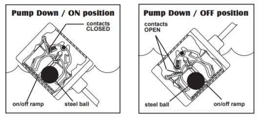
Help me sanity check my float switch for my tanks on the hill. I think it's backwards from what I want. Here's the specs and diagram. I bought it locally so I can just exchange it if it's wrong. The well guy seemed to be a little unsure as he sold it to me...

For reference, I have a controller box above the well with some lights that change as the well pump operates. I also have it going through a good sized relay in the guest house's water heater closet. Do you think closing the circuit on the existing float switch activates the pump?

https://rainwaterequipment.com/sje-PUMPMASTER-plus-pump-up-switch-without-plug-15-cable/

https://rainwaterequipment.com/content/documentation/SJE-Pump-Master-specs.pdf

80-pump_float_switch_diagram_193977f747386bf74a5b4eacf7a31e7d37e33898.jpg
 

Bannerman

Well-Known Member
Messages
4,847
Reaction score
792
Points
113
Location
Ontario, Canada
Do you think closing the circuit on the existing float switch activates the pump?
'Closing the circuit' commonly means the switch will be allowing power to pass through, to supply power to the pump. It appears you want a switch that will close the circuit when the float is in the down position.

The diagram shown is commonly used for a sump pump, to activate the pump when the float is raised and to shut off the pump when the water level in the sump is low. This operation is opposite to what you need to fill your water storage tank.
 
Last edited:

Reach4

Well-Known Member
Messages
38,892
Reaction score
4,436
Points
113
Location
IL
Help me sanity check my float switch for my tanks on the hill. I think it's backwards from what I want. Here's the specs and diagram. I bought it locally so I can just exchange it if it's wrong. The well guy seemed to be a little unsure as he sold it to me...

For reference, I have a controller box above the well with some lights that change as the well pump operates. I also have it going through a good sized relay in the guest house's water heater closet. Do you think closing the circuit on the existing float switch activates the pump?

https://rainwaterequipment.com/sje-PUMPMASTER-plus-pump-up-switch-without-plug-15-cable/
That one in the first url would be the correct thing to control the pump to control the pump that fills the tank . ("pump up")

The opposite kind as shown in the drawing, that empties a sump/tank, would be called a "pump down" type. That could also be the one that would be used in the cistern/tank to prevent a pressure pump from running when the cistern/tank is empty

You want one with "PU" in the model number, rather than "PD", to control the pump that fills the tank.
 
Last edited:
Top
Hey, wait a minute.

This is awkward, but...

It looks like you're using an ad blocker. We get it, but (1) terrylove.com can't live without ads, and (2) ad blockers can cause issues with videos and comments. If you'd like to support the site, please allow ads.

If any particular ad is your REASON for blocking ads, please let us know. We might be able to do something about it. Thanks.
I've Disabled AdBlock    No Thanks