How to Repipe

Users who are viewing this thread

Messages
32
Reaction score
0
Points
6
Location
Kansas
The tub drain is wrong, you have an S trap going into a san tee on its back. Neither is up to code. Also, the die cast slip joint nut is about corroded off and the top one is missing. I would use brass nuts.

Your problem with a combo and elbow being too high can be solved by using a wye and an elbow.

You can download and print isometric graph paper which makes it much easier and neater to draw. You will probably need to study up a bit to know how to use it.

Thank you for the great info. That is the kind of helpful stuff I’m looking for.

Actually, Jeff, I printed isometric paper and tried to do it. I couldn’t figure it out with all the different angles, and the horizontal pipe going straight up to a toilet, along with some other things.

Therefore, I made a video. It is narrated and shows all the piping that can be seen with the walls open, except the showers (which I posted pictures of). It also shows the actual bathrooms, and where everything is located.

Basically, the two toilets are back to back with a wall between them. The two showers are back to back with a wall between them. The two sinks are back to back with a wall between.

To the right of the ABS saddle valve in the video is where it goes up to the roof vent, but goes to the 2 sinks on the way up.

Here is the video link. I am also attaching a picture of the vertical pipe in the attic going to the roof vent.


I wonder why that roof vent didn’t go straight up? Maybe they already made the cut in the roof before knowing exactly where the pipe was going to come out? Is that an issue?
 

Attachments

  • C18D9A87-E61E-4710-A7BC-632A0F1FE4C2.jpeg
    C18D9A87-E61E-4710-A7BC-632A0F1FE4C2.jpeg
    103.2 KB · Views: 129

wwhitney

In the Trades
Messages
6,532
Reaction score
1,822
Points
113
Location
Berkeley, CA
As I mentioned earlier, I think an approximately to scale floor plan showing all the fixture locations, the walls, the direction the joists go, and all the pipes you know about is the proper starting point for redesign. Risers show up in cross section as circles. If you show the vents, perhaps make their horizontal segments as dashed lines or a different color to distinguish their higher elevation.

Cheers, Wayne
 

Jeff H Young

In the Trades
Messages
8,766
Reaction score
2,169
Points
113
Location
92346
As I mentioned earlier, I think an approximately to scale floor plan showing all the fixture locations, the walls, the direction the joists go, and all the pipes you know about is the proper starting point for redesign. Risers show up in cross section as circles. If you show the vents, perhaps make their horizontal segments as dashed lines or a different color to distinguish their higher elevation.

Cheers, Wayne
Agree I been trying to tell him same thing
 
Messages
32
Reaction score
0
Points
6
Location
Kansas
I know what was said. I said I tried to make an isometric drawing, and it didn’t come out right. I have tried multiple times. I am not going to spend several days learning isometric drawings for something like that. It isn’t necessary. That is why there is a video, pictures, and the best drawing of what I have. If I was a plumber in your situation, I would be telling the poster helpful things like, you should replace the s-traps with p-traps and replace the sanitary tee with (fill in the blank). I would tell you things like, if there is a vent on the next branch of the horizontal drain, that will be sufficient for venting the 2 toilets. That, or the venting is not sufficient. Then, I would know what to do, or could ask follow-up questions.

Just because I don’t have any training or previous experience with isometric drawings, does not mean I can’t tackle this job.

What I have provided visually shows you all the piping I can see. If you want the dimensions of the bathrooms, that is fine.

The length of each pipe can be cut and fitted as they are replaced. All visible piping is in the video, minus the showers, which you can see are s-traps with sanitary tees.
 

wwhitney

In the Trades
Messages
6,532
Reaction score
1,822
Points
113
Location
Berkeley, CA
I see in post #18 I mentioned isomteric drawing, perhaps that was a mistake, and I'm sorry it has caused some confusion. Let me clarify now:

A floor plan is just a 2-D drawing. Like a map, it's from an overhead point of view, except without the perspective. It's a horizontal cross section, and only shows 2 dimensions. Often referred to as "plan view," in contrast to an elevation, which is a 2-D projection with one horizontal and one vertical dimension.

An isometric drawing is a way of representing 3 dimensions on a page. It's mostly useful in this context for piping systems where the pipes are just represented as lines.

For a new design, it's best to start with a floor plan. An isometric might be useful to clarify a tricky section of the new piping where only 2 dimensions at a time doesn't really show what is going on very well. Or an isometric can be used to describe all the existing piping.

To be honest, I haven't looked at your videos. For the information required, video is an inefficient way to communicate; if I watched it, the first thing I would do is try to generate a floor plan from it. Which is something you can do much more easily and more accurately.

So if you can provide a floor plan (not an isometric), then we can advise you on how the DWV should be rebuilt.

Cheers, Wayne
 
Last edited:
Messages
32
Reaction score
0
Points
6
Location
Kansas
I see in post #18 I mentioned isomteric drawing, perhaps that was a mistake, and I'm sorry it has caused some confusion. Let me clarify now:

A floor plan is just a 2-D drawing. Like a map, it's from an overhead point of view, except without the perspective. It's a horizontal cross section, and only shows 2 dimensions. Often referred to as "plan view," in contrast to an elevation, which is a 2-D projection with one horizontal and one vertical dimension.

An isometric drawing is a way of representing 3 dimensions on a page. It's mostly useful in this context for piping systems where the pipes are just represented as lines.

For a new design, it's best to start with a floor plan. An isometric might be useful to clarify a tricky section of the new piping where only 2 dimensions at a time doesn't really show what is going on very well. Or an isometric can be used to describe all the existing piping.

To be honest, I haven't looked at your videos. For the information required, video is an inefficient way to communicate; if I watched it, the first thing I would do is try to generate a floor plan from it. Which is something you can do much more easily and more accurately.

So if you can provide a floor plan (not an isometric), then we can advise you on how the DWV should be rebuilt.

Cheers, Wayne

I have attached another drawing. Watching the 2 minute video would have been helpful. There is roughly 3 feet of space between each fixture in their respective bathrooms. The roof vent is between the 2 sinks and goes to the roof.
 

Attachments

  • D15F0359-583A-4F66-A2C3-51A80D6D377B.jpeg
    D15F0359-583A-4F66-A2C3-51A80D6D377B.jpeg
    58.1 KB · Views: 127

wwhitney

In the Trades
Messages
6,532
Reaction score
1,822
Points
113
Location
Berkeley, CA
Excellent.

Just a couple more things needed on the diagram: where is the current downstream drain that everything needs to tie into? Which way do the floor joists run (and if a joist is really close to either closet flange for the toilets, where exactly is it)? And do I infer correctly from the photos that part of the area below has a ceiling tight to the floor joists, while part of it has a ceiling farther down, that permits pipes to run beneath the floor joists but above the ceiling?

Cheers,
Wayne
 
Messages
32
Reaction score
0
Points
6
Location
Kansas
Excellent.

Just a couple more things needed on the diagram: where is the current downstream drain that everything needs to tie into? Which way do the floor joists run (and if a joist is really close to either closet flange for the toilets, where exactly is it)? And do I infer correctly from the photos that part of the area below has a ceiling tight to the floor joists, while part of it has a ceiling farther down, that permits pipes to run beneath the floor joists but above the ceiling?

Cheers,
Wayne

The just run between bathrooms. I added some in the picture. The piping for the toilet in the bigger bathroom is right in between the joists. The toilet in the small bathroom is 2 or 3 inches closer to one of the joists.

The downstream horizontal run is directly below the toilet in the larger bathroom. It goes downstream from there, where it hits in elbow and goes down to the basement.

I would recommend watching the video. It will make things clear.
 

Attachments

  • 82E72E3B-085F-45D1-AF9F-33257C1E7611.jpeg
    82E72E3B-085F-45D1-AF9F-33257C1E7611.jpeg
    65.1 KB · Views: 127

wwhitney

In the Trades
Messages
6,532
Reaction score
1,822
Points
113
Location
Berkeley, CA
Great. With your drawing I can much more easily put all the pictures together, and correlate that with the video you shot, which was helpful.

One question now: in the first several photos in the thread, the horizontal 3" pipe looks to be directly under the large bathroom closet flange and runs perpendicular to and below the joists. What's the clear horizontal distance between the wall studs separating the two rooms on the floor below and that 3" pipe? I infer that the wall below is not underneath the wall above between the two bathrooms.

It may be necessary to get a photo of the sink drains in the joist bay shown on the far right in the second photo of the thread. Also, pictures of the DWV under each sink would be helpful--if there's a cleanout that would tell us something about the pipe size there, and if there are trap adapters near the wall, then the traps could be easily removed and you could see what sort of fitting(s) are in the wall, and hopefully confirm the dry vent that rises up between the sinks.

Your double bathroom layout is very standard, and if the ceilings were open and you wanted to run the DWV within the joists and could drill them, it would be a pretty standard design. But you currently have all the DWV running perpendicular to the joists in that soffit in the room below, so I expect you want to keep it there. And not drill any joists, and not open up any drywall upstairs if possible.

So that's definitely an interesting design challenge and I will give it some more thought. If we confirm the sinks are dry vented, then using them to wet vent the WCs is not hard. The tub and shower are more challenging to properly vent, because the drain below the joists is too low to use to wet vent their traps.

Cheers, Wayne
 

wwhitney

In the Trades
Messages
6,532
Reaction score
1,822
Points
113
Location
Berkeley, CA
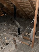
Okay, I've given it some thought and here are the best options I've come up with. I'm going to assume that you want to leave the 3" line located in the soffit as it currently is. And that upstream of the bend shown in the 2nd photo in the thread (which should be a LT90, can't tell from the photo) are the two lav drains, which are vented through the roof (to be confirmed).

First, an important building code note: the area above that soffit is not properly fireblocked. The point of fireblocking here is so that if fire gets into one of the stud bays, it does not immediately rise up the bay into the soffit and spread to all the floor joist bays. So each stud bay is supposed to be closed off so it doesn't communicate with the soffit or any of the joist bays. For details, see:

https://up.codes/viewer/kansas/irc-2018/chapter/3/building-planning#R302.11

Second, how to run the two WC drains so they are properly vented? The 3" horizontal line in the soffit can vent each WC, since the IPC (in use in Kansas) allows up to two bathroom groups on a single horizontal wet vent. And since WCs have an integral trap, there's no regulation of the elevation at which the WC fixture drain joins the 3" horizontal line.

But the two WCs do have to be kept separate. So if running the outlet of the far WC's closet bend parallel to the joists would cause it to run under the closer WC's closet flange, the far WC drain should offset to one side or the other within the joist bay. E.g. by rotating the closet bend so its ouput is at a 22.5 or 45 degree angle to the joists, and then using a 22.5 or 45 degree elbow to turn to parallel to the joists (and to line up as required for later connection to the 3" horizontal line in the soffit, see below).

Then the only remaining question is how to connect each WC fixture drain to the 3" horizontal line. It needs to be with a wye (or combo), not a san-tee on its back. And separately, so you'll need (2) 3" wyes. If space is tight, you may want the upstream wye to be street so it can connect directly to the downstream wye.

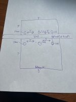
Now there is some difference of opinion about the allowable orientation of that wye's branch inlet for horizontal wet venting. Some say that the wye can have the inlet on top. Then on the near WC (directly over the 3" horizontal soffit line) you can just use a 45 below the flange to hit an upright wye (or just use an upright combo), and on the far WC drain you'd just need to use a quarter bend on the horizontal line, with the outlet turned 45 degrees off plumb and pointed at the wye.

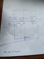
But there is also a school of thought that the wye needs to "horizontal" for horizontal wet venting. In that case I would think it would be OK to roll the wye 45 degrees off vertical, as then its inlet would be considered horizontal. With a wye in that orientation, a 60 degree bend on the branch inlet will either get you to vertical, or horizontal perpendicular to the joists (not useful here); and a 45 would get you horizontal parallel to the barrel of the wye (always possible, not dependent on how much the wye is rolled). So the near WC drain could jog away from the wall with two 45s, then the vertical would hit a 60 to hit the wye rolled up 45 degrees. And the far WC drain would run slightly beyond the 3" horizontal soffit drain, then hit a quarter bend rolled 45 degrees, then a 45 degree to go horizontal, parallel to the 3" horizontal soffit line, with a 45 and wye to join the 3" horizontal soffit line.

Getting all of the above to fit in one joist bay may be a bit of a challenge without hitting the joists. The challenge would probably be minimized by having the horizontal line coming from the far WC cross over the top plate as low as possible (maybe minimum 1/4" clearance). That way the first fitting on that line will more quickly enter the unconstrained soffit area under the joists. But depending on the height required for some of the above fitting configurations, you may need to have the far WC fixture drain higher up in the joist bay, assuming that it will fit without hitting the joists.

More to follow.

Cheers, Wayne
 
Last edited:

wwhitney

In the Trades
Messages
6,532
Reaction score
1,822
Points
113
Location
Berkeley, CA
Third and finally, how to connect the shower and tub drains while properly venting them and avoiding an S-trap? The venting rules for the shower and tub traps require that the trap arm coming out of the trap elbow stay horizontal, sloped at least 1/4" per foot, but falling no more than one pipe internal diameter before the vent is connected. And that vent can either be a dry vent connected to the top half of the drain, or a wet vent connected horizontally or on top.

So I see 3 options, none ideal but all plausible:

1) Use the horizontal 3" soffit drain to wet vent the tub and the shower. Because of the limit on the fall of a trap arm, you'd need to install a soffit in the other room so each trap outlet can be below the joists (with the trap arms penetrating the wall below the double top plate). The shower and tub trap arms would be kept separate and each join the 3" horizontal soffit drain with a wye or combo, with the side inlet at 1/4" per foot slope. [Combos are not available street, so if you want keep the two connections as tight to each other as possible on the 3" line, you could use a 3" street wye connected to a 3" combo.]

2) Use one lav drain to wet vent the tub and shower. This would require you to do some surgery to separate the two lav drains (but they could share the existing vent through the roof). One lav drain would connect to the 3" horizontal soffit drain as currently, to wet vent the WCs (and it could be a 1-1/2" drain from that lav up to the connection to the WCs). The other lav drain would need to be run through new holes drilled through the joists (a 1-1/2" drain, so 2-1/4" holes would work, each hole at least 2" clear from the top or bottom of the joist). That lets the lavatory drain come into the joist bay with the tub and shower drains at a height that would allow the tub and shower traps to be up in the joist bay. The lav drain would join either the tub or shower; then the 2" joint drain would meet up with the other of the tub and shower; then the 2" drain would proceed to over the 3" horizontal soffit drain and connect to it (which can be via a quarter bend turned 45 degrees off plumb pointed at a upright wye.)

3) Dry vent the tub or shower, and use that to wet vent the other. The vent takeoff could be an upright wye on one of the trap arms; then the two parallel fixture drains could join on the horizontal via a wye plus 45. Or the vent takeoff could be via a san-tee (with the barrel upright, or the barrel at 45 degrees off plumb and a street 45 on the inlet to provide a plumb vent takeoff), with another san-tee below that for the other trap arm (so the two trap arms would not be at the same elevation).

The main question with this option is what to do with the dry vent? An AAV is an option, and only needs to be 4" above the trap arm; but I'm not sure if putting an AAV in a box in the floor joist system with a ventilated access panel would be allowable option. Otherwise, you'd need to figure out how to extend the dry vent pipe up into one of the walls above (while staying vertical, meaning at most 45 degrees off plumb) and either bring it to an AAV in a wall box, or bring it up into the attic to join the vent for the lavs.

Cheers, Wayne
 
Messages
32
Reaction score
0
Points
6
Location
Kansas
Third and finally, how to connect the shower and tub drains while properly venting them and avoiding an S-trap? The venting rules for the shower and tub traps require that the trap arm coming out of the trap elbow stay horizontal, sloped at least 1/4" per foot, but falling no more than one pipe internal diameter before the vent is connected. And that vent can either be a dry vent connected to the top half of the drain, or a wet vent connected horizontally or on top.

So I see 3 options, none ideal but all plausible:

1) Use the horizontal 3" soffit drain to wet vent the tub and the shower. Because of the limit on the fall of a trap arm, you'd need to install a soffit in the other room so each trap outlet can be below the joists (with the trap arms penetrating the wall below the double top plate). The shower and tub trap arms would be kept separate and each join the 3" horizontal soffit drain with a wye or combo, with the side inlet at 1/4" per foot slope. [Combos are not available street, so if you want keep the two connections as tight to each other as possible on the 3" line, you could use a 3" street wye connected to a 3" combo.]

2) Use one lav drain to wet vent the tub and shower. This would require you to do some surgery to separate the two lav drains (but they could share the existing vent through the roof). One lav drain would connect to the 3" horizontal soffit drain as currently, to wet vent the WCs (and it could be a 1-1/2" drain from that lav up to the connection to the WCs). The other lav drain would need to be run through new holes drilled through the joists (a 1-1/2" drain, so 2-1/4" holes would work, each hole at least 2" clear from the top or bottom of the joist). That lets the lavatory drain come into the joist bay with the tub and shower drains at a height that would allow the tub and shower traps to be up in the joist bay. The lav drain would join either the tub or shower; then the 2" joint drain would meet up with the other of the tub and shower; then the 2" drain would proceed to over the 3" horizontal soffit drain and connect to it (which can be via a quarter bend turned 45 degrees off plumb pointed at a upright wye.)

3) Dry vent the tub or shower, and use that to wet vent the other. The vent takeoff could be an upright wye on one of the trap arms; then the two parallel fixture drains could join on the horizontal via a wye plus 45. Or the vent takeoff could be via a san-tee (with the barrel upright, or the barrel at 45 degrees off plumb and a street 45 on the inlet to provide a plumb vent takeoff), with another san-tee below that for the other trap arm (so the two trap arms would not be at the same elevation).

The main question with this option is what to do with the dry vent? An AAV is an option, and only needs to be 4" above the trap arm; but I'm not sure if putting an AAV in a box in the floor joist system with a ventilated access panel would be allowable option. Otherwise, you'd need to figure out how to extend the dry vent pipe up into one of the walls above (while staying vertical, meaning at most 45 degrees off plumb) and either bring it to an AAV in a wall box, or bring it up into the attic to join the vent for the lavs.

Cheers, Wayne

Thanks for all the great info. I read it over a few times. I am going to look at my plumbing tomorrow and associate it with what you said. I will get back to you with follow-up questions.
 
Messages
32
Reaction score
0
Points
6
Location
Kansas
It looks like there is about 14 1/2 inches between the two joists in that bay. There are also 2 copper water pipes above the 3 inch horizontal drain, as you can see in the picture with the WC right above the 3 inch horizontal drain. What do you think the best configuration for the 2 WCs is? You mentioned 2 different scenarios, based on schools of thought.

Am I understanding correctly that in one scenario that the wye would be pointing upwards, and the other scenario, the wye would be rolled 45 degrees so it would be horizontal?

I’m guessing the only spot I will have space to run the farther back WC would be where the 1 1/2 inch line is currently, by removing it and running my 3 inch line there?

Since replacing the ABS that goes to the sinks, and the ABS that continues downstream to the sewer main isn’t part of the replacement plan, how will I replace the pipes, in between, and connect them to where they bottom out with each other, without using something like a Fernco?

Thanks.
 

wwhitney

In the Trades
Messages
6,532
Reaction score
1,822
Points
113
Location
Berkeley, CA
Am I understanding correctly that in one scenario that the wye would be pointing upwards, and the other scenario, the wye would be rolled 45 degrees so it would be horizontal?
When the barrel path on a wye is horizontal (2% slope), going from the side branch vertical-most (45 degrees off plumb) to horizontal (2% slope) requires rolling 90 degrees. Connecting to the horizontal wye is a possibility, you'd just need more elbows to do that. Which is why I suggested rolling the wye only 45 degrees. Which makes the geometry trickier, but should allow a connection with fewer degrees of bend and possibly taking up less space.

I’m guessing the only spot I will have space to run the farther back WC would be where the 1 1/2 inch line is currently, by removing it and running my 3 inch line there?
Sounds plausible. Certainly that 1-1/2" saddle line is doing nothing, as long as you are sure it only connects to those two 3" lines and doesn't have an additional connection to a vent. [If it does have an additional connection to a vent, the 1-1/2" saddle line still should be removed, but the remaining vent could be of use.]

Since replacing the ABS that goes to the sinks, and the ABS that continues downstream to the sewer main isn’t part of the replacement plan, how will I replace the pipes, in between, and connect them to where they bottom out with each other, without using something like a Fernco?
You won't. You just need to use the correct type of rubber coupling, which is fully shielded and rated for above ground use, e.g. Fernco Proflex.

Cheers, Wayne
 
Messages
32
Reaction score
0
Points
6
Location
Kansas
When the barrel path on a wye is horizontal (2% slope), going from the side branch vertical-most (45 degrees off plumb) to horizontal (2% slope) requires rolling 90 degrees. Connecting to the horizontal wye is a possibility, you'd just need more elbows to do that. Which is why I suggested rolling the wye only 45 degrees. Which makes the geometry trickier, but should allow a connection with fewer degrees of bend and possibly taking up less space.


Sounds plausible. Certainly that 1-1/2" saddle line is doing nothing, as long as you are sure it only connects to those two 3" lines and doesn't have an additional connection to a vent. [If it does have an additional connection to a vent, the 1-1/2" saddle line still should be removed, but the remaining vent could be of use.]


You won't. You just need to use the correct type of rubber coupling, which is fully shielded and rated for above ground use, e.g. Fernco Proflex.

Cheers, Wayne

So the wye will be 45 degrees pointed towards the back WC?

The reason I didn’t use the pro flex couplings was two fold. One, it seemed like one side fit cast iron, and didn’t fit the ABS. Two, it had a rubber stopper in the middle. I can’t slide it completely over one pipe, butt up the other pipe, and then slide it halfway between both connections. I don’t see how that will work. Any thoughts.

I think I want to implement solution #1 for the shower and tub. I’m not able to visualize how to pipe things based off what you said, in that scenario. Could you make a rough drawing, or help me another way?

Thanks.
 

wwhitney

In the Trades
Messages
6,532
Reaction score
1,822
Points
113
Location
Berkeley, CA
On the proflex, 3005 is the series for plastic to plastic connections, so 3005-33 is for 3" to 3". And what you do is put the coupling on one end of the pipe, slide the metal shield farther down, and fold the empty rubber socket back over the the pipe end as well.

So if you are installing a length of pipe between two fixed cut ends of pipe, you'd size the length to be about 3/8" shorter than the clear space between the two fixed ends, and use 2 couplings. The 3/8" represents 1/8" x 2 for the two stops, and another 1/8" for some wiggle room, because the folded back rubber still sticks out past the stop a little.

Cheers, Wayne
 
Top
Hey, wait a minute.

This is awkward, but...

It looks like you're using an ad blocker. We get it, but (1) terrylove.com can't live without ads, and (2) ad blockers can cause issues with videos and comments. If you'd like to support the site, please allow ads.

If any particular ad is your REASON for blocking ads, please let us know. We might be able to do something about it. Thanks.
I've Disabled AdBlock    No Thanks