Can water flow through circulator pump when it is not running?

Users who are viewing this thread

CheesecakeLover

New Member
Messages
23
Reaction score
1
Points
3
Location
Hopatcong, NJ
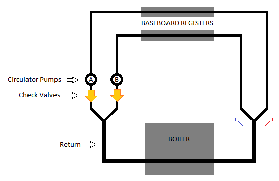
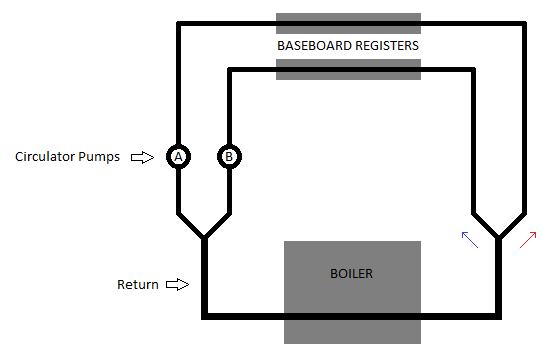
In a system with a circulator pump for each zone, do we also need zone valves, or will the pumps themselves block water from flowing through them when they are "off"?

For example, say there are 2 pumps:
  • Zone A pump.
  • Zone B pump.
  • (And no valves)
If Zone A pump is running and Zone B pump is not running, will water be pushed into Zone B anyway?

See diagram... Will water only go into Zone A (red arrow), or will some water also go into Zone B (blue arrow)?

OJ3mDKR.png
 
Last edited:

Dana

In the trades
Messages
7,889
Reaction score
511
Points
113
Location
01609
If pump A is pumping toward the boiler it will be depressurizing the wye at the right side of the diagram, and pressurizing the wye at the left. That will force flow back through pump B toward the right side. If the pumping head of the boiler is an order of magnitude lower than the B-pump branch that may not matter very much- pump B will spin very slowly in reverse, and the flow will be quite limited. If it's a higher head boiler there could be enough flow for measurable amounts of heat to be emitted from the B-zone baseboard.

With check valves at the outputs of the pumps (recommended) that doesn't happen. Many pumps come with integrated check valves that can either be installed or not, depending on the applications. Most of Taco's circulators pumps almost always come the "IFC" check valve, but many hacks wrenching on hydronic systems seem to toss 'em out. If it turns out you need one they are sold separately, and are cheaper than a check valve as a completely separate component.
 

CheesecakeLover

New Member
Messages
23
Reaction score
1
Points
3
Location
Hopatcong, NJ
Dana, thank you for the thoughtful response. So to make sure I understand you, I updated the diagram to include check valves.

mvEhpxa.png


With check valves installed now, water can't travel backwards through pump B. But I still have a question about the wye on the right side of the diagram. Could water still push into the B side of the wye (blue arrow) even if pump B is "off"?

I guess the core of my question is whether an unpowered circulator pump can act as a "closed valve", thereby eliminating the need to have traditional zone valves.
 

NY_Rob

In the Trades
Messages
317
Reaction score
26
Points
28
Location
New York
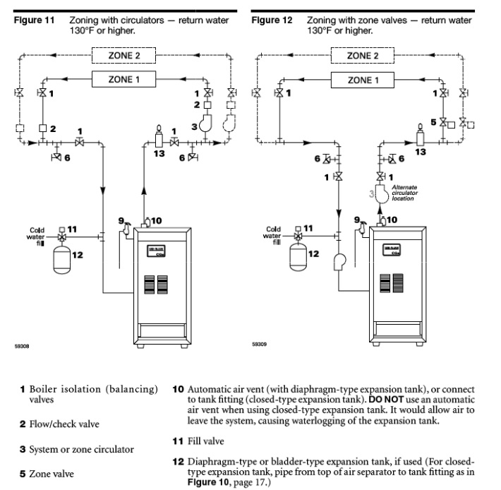
FWIW- many modern boiler manufacturers recommend "pumping away" from the boiler, ie the pumps should be on the right side of your diagram. Check the install manual for your particular boiler to be sure as some still pump to the boiler.

Pumping-Away.jpg
 

Dana

In the trades
Messages
7,889
Reaction score
511
Points
113
Location
01609
NY_Rob: Most modern boilers aren't anything like that cast iron dinosaur in the diagram. Water tube mod-cons have somewhat higher head, and you're better off pumping TOWARD the boiler. Pumping toward the boiler makes it the highest pressure location on the loop, reducing any propensity for flash-boil/kettling in the heat exchanger. Placing the expansion tank near the intake side of the pump acts a bit like a shock absorber, reducing cavitation wear on the impeller, and minimizes pressure pump cavitation vibrations from pulling air into the system from system vents.

Pumping away from the expansion tank is the most important aspect. With old-school cast iron like that with a pre-plumbed port dedicated to the expansion tank, pumping away from the boiler was the same as pumping away from the expansion tank.

Cheesecakelover: In the new diagram the pressure difference at pump B is still in the reverse direction when pump A is running. A pump is not a closed valve- when unpowered the impeller spins freely in either direction when there is a pressure difference across the pump. With a pump on each zone there is no need for a zone valve, just a check valve will do. Zone valves are for limiting the number of pump$, and reducing overall electricity use in the system.
 

CheesecakeLover

New Member
Messages
23
Reaction score
1
Points
3
Location
Hopatcong, NJ
Dana, sorry I don't understand. With a check valve shielding pump B from backward flow, how can there be reverse pressure at pump B?

In addition, you mention that when unpowered the pump impeller spins freely, therefore an unpowered pump does not block water. Yet you also said that no zone valves are needed if you have a pump on each zone? I can't rectify these seemingly contradicting points in my head because if the unpowered pumps don't block the water, what is preventing hot water from entering a zone other than the one it is intended for? Please help me understand.

NOTE: I currently have a old Weil-Mclain cast iron boiler, and with 1 circulator pump on the return side of the boiler. The expansion tank is (perhaps incorrectly) located on the outflow side of the boiler.

Another Note: I am not planning on making any changes to my current heating system. I am one of those guys who likes to dream of how I would set things up in my "dream house" in the future when I win the lottery and have tons of money to blow. I have had several zone valves fail over the years and a system that contains multiple circulator pumps but zero zone valves sounds appealing to me.
 
Last edited:

Dana

In the trades
Messages
7,889
Reaction score
511
Points
113
Location
01609
Dana, sorry I don't understand. With a check valve shielding pump B from backward flow, how can there be reverse pressure at pump B?

Perhaps we're getting hung up on semantics. The reverse pressure is blocked by the check valve, so there is no reverse flow. But that is the direction of the pressure differential.

In addition, you mention that when unpowered the pump impeller spins freely, therefore an unpowered pump does not block water. Yet you also said that no zone valves are needed if you have a pump on each zone? I can't rectify these seemingly contradicting points in my head because if the unpowered pumps don't block the water, what is preventing hot water from entering a zone other than the one it is intended for? Please help me understand.

Water doesn't move until and unless something is creating a pressure difference. If reverse flows are being blocked by check valves on every zone, and there is no reverse pressure or flow at the pump, and there is no pressure in the positive direction being induced. The water in the off zone just sits there- it can't be sucked out at the wye at the right side of the diagram with the check valve at pump B, but if that valve were absent it would backflow on the pressures induced by pump A. The pump doesn't block the flow, the check valve does.

In some messy primary/secondary systems there can sometimes be a slight forward pressure on "off" zones induced by the primary pump, enough to spin the pump in the forward direction, but only rarely to the point of needing a zone valve.

NOTE: I currently have a old Weil-Mclain cast iron boiler, and with 1 circulator pump on the return side of the boiler. The expansion tank is (perhaps incorrectly) located on the outflow side of the boiler.

Yours and thousands of others are built that way and still working just fine. But from "best practices" perspective it's better to put the expansion tank at the input side of the pump, whether it's pumping toward or away from the boiler. But it gets complicated quickly when there are multiple pumps with different functions in different parts of the system (primary/secondary, multiple secondary loops etc.) which begs the question Pumping Away From What?

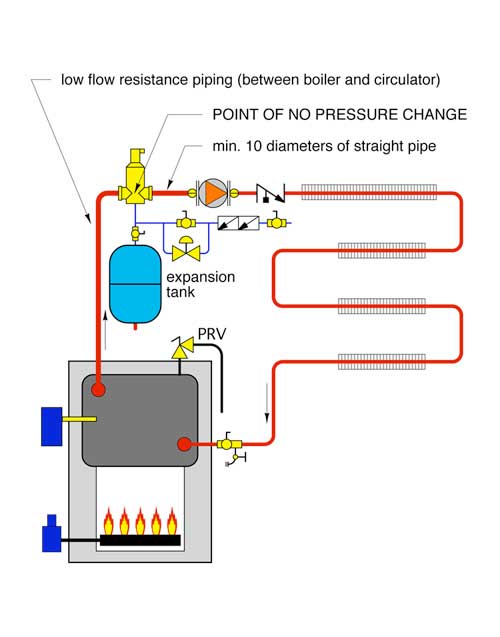
With the very low head of a cast iron boiler like yours the expansion tank can reside in either side of the boiler, and as long as the pump is pumping away from the tank (even with the boiler in-between) the expansion tank is still protecting the pump if the pump is pumping away. So yours isn't ideal- don't sweat the small stuff. As long as it isn't chewing through pumps every few years and not sucking air into the system it's fine, no need to mess with it. But this is sort of the classic new-school recommendations for low head boilers like yours:

0909pm-Sieg-fig1-lg.jpg


(The sideways Z symbol to the right of the pump is the standard for a check valve, not that it's really necessary in this one loop system.)

Another Note: I am not planning on making any changes to my current heating system. I am one of those guys who likes to dream of how I would set things up in my "dream house" in the future when I win the lottery and have tons of money to blow. I have had several zone valves fail over the years and a system that contains multiple circulator pumps but zero zone valves sounds appealing to me.

Newer "smart" ECM drive pumps programmed for constant-pressure feedback aren't as abusive to zone valves as typical split capacitor drive circulators, since the velocity of the water through any individual zone valve is never too high. With an old school pump and only one zone open the gpm through the valve can be pretty high, and the water-hammer when it closes can be pretty hard. With a smart pump it all gets dialed down, the pump speed/power rises and falls with then number of active zones.
 
Last edited by a moderator:

CheesecakeLover

New Member
Messages
23
Reaction score
1
Points
3
Location
Hopatcong, NJ
Water doesn't move until and unless something is creating a pressure difference. If reverse flows are being blocked by check valves on every zone, and there is no reverse pressure or flow at the pump, and there is no pressure in the positive direction being induced. The water in the off zone just sits there- it can't be sucked out at the wye at the right side of the diagram with the check valve at pump B, but if that valve were absent it would backflow on the pressures induced by pump A. The pump doesn't block the flow, the check valve does.
Got it, thanks. Yeah this part I understood.

In some messy primary/secondary systems there can sometimes be a slight forward pressure on "off" zones induced by the primary pump, enough to spin the pump in the forward direction, but only rarely to the point of needing a zone valve.
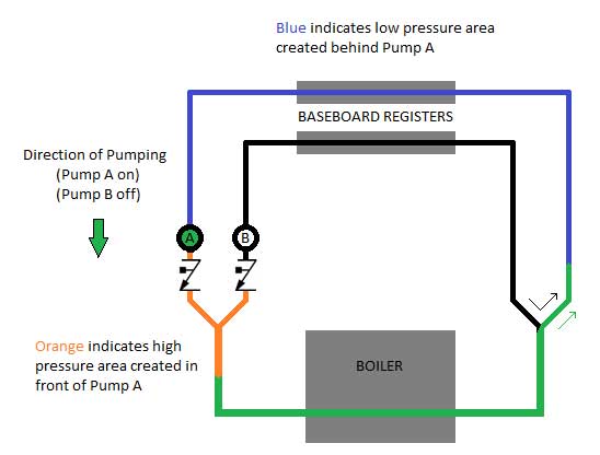
I think what you wrote here really zeroed in on my question. So basically what I'm taking away (and please correct me if I'm still getting this wrong) is...
  1. An inactive circulator pump does not block water, so water could flow through it, in whatever direction the pressure drives the flow.
  2. In this case, if Pump A is "on" and Pump B is "off":
    • Pump A creates a high-pressure area in front of it (orange). Some of this water would flow backward through Pump B, but cannot do so because the Pump B is protected by a check valve. Therefore all the water must flow through the boiler.
    • Simultaneously, Pump A also creates a low-pressure area behind it (blue). Therefore water after the boiler will flow into this low-pressure area (following the green arrow) in order to equalize.
    • The water in the B loop (black) would want to flow into the low-pressure (blue) area (following the black arrow), but it cannot do so because check valve B won't allow any water to take its place.
GzfuMyw.jpg
 
Last edited by a moderator:

Frandy

New Member
Messages
3
Reaction score
0
Points
1
Location
Parsippany
Got it, thanks. Yeah this part I understood.


I think what you wrote here really zeroed in on my question. So basically what I'm taking away (and please correct me if I'm still getting this wrong) is...
  1. An inactive circulator pump does not block water, so water could flow through it, in whatever direction the pressure drives the flow.
  2. In this case, if Pump A is "on" and Pump B is "off":
    • Pump A creates a high-pressure area in front of it (orange). Some of this water would flow backward through Pump B, but cannot do so because the Pump B is protected by a check valve. Therefore all the water must flow through the boiler.
    • Simultaneously, Pump A also creates a low-pressure area behind it (blue). Therefore water after the boiler will flow into this low-pressure area (following the green arrow) in order to equalize.
    • The water in the B loop (black) would want to flow into the low-pressure (blue) area (following the black arrow), but it cannot do so because check valve B won't allow any water to take its place.
So in this scenario, would pump A and B need to be equally sized? I currently have a 1/25 on loop B and a 1/8 on loop. My problem is that Loop A works fine. but Loop B doesn’t turn on the Boiler when it turns on. When pump A and B engage I can see the flow rate increase but all the water seems to flow over loop A.
 
Last edited by a moderator:

Dana

In the trades
Messages
7,889
Reaction score
511
Points
113
Location
01609
So in this scenario, would pump A and B need to be equally sized? I currently have a 1/25 on loop B and a 1/8 on loop. My problem is that Loop A works fine. but Loop B doesn’t turn on the Boiler when it turns on. When pump A and B engage I can see the flow rate increase but all the water seems to flow over loop A.

I'm assuming you have check valves?

The amount of pumping head on each loop affects things, but when pump A has ~4x the power of pump-B and the loop has moderate to high pumping head in the commoned section through the boiler (between the Ys) pump A may impart enough back pressure to measurably lower the flow on pump B's loop.

If it's a cast-iron boiler the burner isn't turned on by the thermostats- the pumps are. The boiler only fires when it's temperature drops to the low-limit, which can take awhile if the flow on the active zone is low, and it's radiation limited.
 

Brayman

New Member
Messages
1
Reaction score
0
Points
1
Location
Northport, NY
Hi Dana, I have similar issue. One of the zones circulate hot water, even if zone is off. I had plumber checked this issue and suggested to put check valve on return line as well. But I do not have enough space to put it after the circulator. Can I install it above circulator pump, where red arrow is on the diagram? Will it work same way? Thank you!
Screen-Shot-2022-01-14-at-9.50.06-PM.jpg
 

Dana

In the trades
Messages
7,889
Reaction score
511
Points
113
Location
01609
A check valve works the same where ever it it positioned within the loop.
 

John Gayewski

In the Trades
Messages
4,727
Reaction score
1,517
Points
113
Location
Iowa
Ghost flows many times isn't stopped with a check valve. Different things other than pressure differential can effect flow. Depending on where the load is, heated water will flow in reverse through convection with no pump running.
 

John Gayewski

In the Trades
Messages
4,727
Reaction score
1,517
Points
113
Location
Iowa
Hi Dana, I have similar issue. One of the zones circulate hot water, even if zone is off. I had plumber checked this issue and suggested to put check valve on return line as well. But I do not have enough space to put it after the circulator. Can I install it above circulator pump, where red arrow is on the diagram? Will it work same way? Thank you!View attachment 80052
No
 

John Gayewski

In the Trades
Messages
4,727
Reaction score
1,517
Points
113
Location
Iowa
This thread got off. There are reasons to pump toward a boiler but they mostly apply to systems with more than 1 boiler or some high head boilers (still most pump away). The air is also extracted from the system at the expansion tank which is added to this whole salad.

Pumping away from the boiler is just short hand for pumping away from the hottest water and the point of no pressure change which also happens to be the best place to scoop the entrained air from the system.

Dana there's no reason to correct someone's drawing/ post then post a drawing that agrees with them. Your just confusing the point. Which was initially correct. I think people with experience are here to clarify not drown people with conflicting info that is outside of their understanding to shift through.
 
Last edited:
Top