2.5 baths from a clean slate

Users who are viewing this thread

M'Arm Strong

New Member
Messages
10
Reaction score
0
Points
1
Location
Ohio
Hey everyone, my name is Michael. I’ve been lurking around here for several years gathering up tons of information from you good folks. A belated thanks is owed to everyone that has indirectly helped me through many home renovation projects.

This year I bought my childhood home and completely gutted it. The new floorplan necessitates all new DWV plumbing. It’s a slab on grade single-story ranch. It was tied into city sewer in 2012 and everything from the foundation to the road is new. It’s located in Ohio and governed by Ohio Plumbing Code, which I understand to be IPC-based.

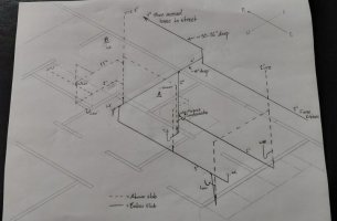
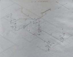
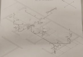
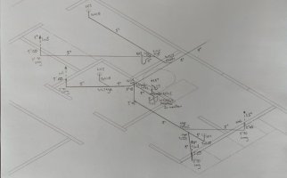
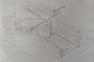
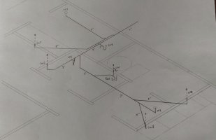
My last whole-house replumb was just one bath and a kitchen, so I could wrap my head around that one pretty easy. The new house is another story. The kitchen is good as-is, but I’m plumbing in 2.5 bathrooms and laundry. I’m trying to minimize cuts in the concrete if possible and hoping to keep the existing roof penetration (hence why some of the lav branches are in the wall). I also have very little space for connecting multiple vent branches in the attic.

I’m comfortable spec’ing pipe sizes and fittings. My main issue is getting the shower (labeled A) and the WC (labeled B) tied in without a ton of bends and without going so deep (because of the vents) that I can’t meet fall requirements when tying to the main. I’ve tried may iterations but haven’t been happy with any of them. The WC is about 7 feet from the double vanity, so I don’t think a wet vent is in the cards.

I know you master plumbers out there will find this one easy! Criticism is welcome on the rest of the layout as well. I’m all about overkill, but if there’s an elegant solution with fewer pipes, I’d love to hear it!

Thanks in advance, and the beers are on me!
 

Attachments

  • Screenshot_20230821_191131_Gallery.jpg
    Screenshot_20230821_191131_Gallery.jpg
    53.5 KB · Views: 87
  • Screenshot_20230821_191152_Gallery.jpg
    Screenshot_20230821_191152_Gallery.jpg
    33.3 KB · Views: 83

wwhitney

In the Trades
Messages
6,567
Reaction score
1,847
Points
113
Location
Berkeley, CA
A few comments:

- IPC does not limit how far the WC fixture drain can run before being wet vented
- IPC allows up to two bathroom groups on a horizontal wet vent. It also does not require WCs to be at the end of the wet vent, they can be anywhere along the line.

So if you number your bathrooms from the bottom right proceeding to the upper left, and the fixtures by what bathroom they are in, Bath 1 has Lav1 and WC1; Bath 2 has Lav2, WC2 and Tub2; and Bath 3 has Lav3, Lav3A, WC3 (labeled B) and Shower3 (labeled A).

You'll need dry vents (or AAVs) at each lav, but you can wet vent all 3 WCs and the shower and tub. Lav1 in Bath 1 can wet vent WC1, Tub2 (connect its drain to the bathroom branch, rather than the washing machine / condensate drain branch), WC2, and Shower3; that eliminates two below slab dry vent takeoffs, and takes care of Shower3's drain and vent. And if you route the Lav3 / Lav3A drain as a 2" drain under the slab towards where the 3" line exits the house, it can join WC3's drain to wet vent it, and then should join the building drain downstream of Shower3.

If you'd like to redraw that, I suggest omitting the dry vent system that are more than 48" above the slab; it's understood they will all combine and go through the roof, and how to do that is usually a separate issue from how to route the underslab plumbing.

Cheers, Wayne
 

M'Arm Strong

New Member
Messages
10
Reaction score
0
Points
1
Location
Ohio
Thanks for the quick, thorough response! This gives me plenty to think about. I'm used to dealing with UPC and IPC seems so lax in comparison. Obviously I'll want to double check to make sure Ohio doesn't have any specific changes to the pertinent parts of your suggestions.

Your layout simplifies things greatly. If I've interpreted it correctly, then the following is true (see drawing):

A. Lav1 wet vents WC1
B. Lav1 wet vents Tub2 (or does main?)
C. "Main" wet vents WC2
- "Main" also serves as the drain and vent for Lav2 (not shown)
D. "Main" wet vents Shower3
E. Lav3,3a are dry vented and wet vent WC3
F. "Wash" Is dry vented
G. WH is dry vented

So now a few more questions because now I really feel outside my wheelhouse haha:

1. Do I need the vent at WH? Or can "Wash" wet vent the condensate trap?
2. Do you see any reason for "Main" to be 3"? Looks like I could reduce it to 2" and reduce that wall section back down to 2x4, buying me 2" more room in the west half of the house (hallway, bedrooms).
3. Does Lav1 need to tie in downstream of Tub2 to properly wet vent it? Does it matter since "Main" could serve the same purpose?
4. Are there any "best practices" that this layout might be violating? It's so simple compared to how complicated I made it lol.

Thanks again for your insight! Please don't take my questioning as pushback, it really is just my ignorance and I'm trying to learn. If I learn the REASONS now, I won't have to ask questions about specifics in the future (hopefully...)

Michael
 

Attachments

  • Screenshot_20230821_223758_Gallery.jpg
    Screenshot_20230821_223758_Gallery.jpg
    36.8 KB · Views: 83

wwhitney

In the Trades
Messages
6,567
Reaction score
1,847
Points
113
Location
Berkeley, CA
1) Unless the condensate trap is under the slab, a drain under the slab can't wet vent it. The vent takeoff always has to be at the elevation of the trap (or within one pipe diameter of fall), as stated. If you replace the condensate trap with a floor drain, then you probably can use the Wash vent to vent the floor trap; I'm not 100% on floor trap rules.

2) Main can be eliminated as a vent for the fixtures drawn; Tub2, WC2, and Shower3 are wet vented by Lav1. If Main is just serving as a drain for Lav2, it and its vent can be 1-1/2". Although there is something to be said for making all under slab drains 2" or larger.

3) No. The combined Lav1/WC1 can wet vent Tub2. If you think of WC1 draining past Tub2 and joining it, Lav1 must connect between WC1 and Tub2 to properly wet vent WC1.

4) Not sure what "best practices" are with regard to venting; some people dislike all wet vents and would dry vent everything; some people think the UPC is better and would stick with those allowances.

[If you want to be UPC compliant, you could make Lav1 drain and vent 2"; use it to wet vent WC1 only. Lav2 drain and vent 2"; use it to wet vent WC2 (which requires that Lav2 joins WC2 before they jointly join Lav1/WC1). Lav3/3a drain and vent 2"; use it to wet vent WC3. Then dry vent Tub2 and use it to wet vent Shower3 (again, the wye where Tub2 joins Shower3 carries no other fixtures). And make sure your WCs are wet vented (location of wye where the lav joins the WC) within 6' of pipe run from the closet flange . And when you aggregate your dry vents, you need to make a 3" roof penetration, or equivalent, like (2) 2" penetrations and (1) 1.5" penetration.]

Cheers, Wayne
 

M'Arm Strong

New Member
Messages
10
Reaction score
0
Points
1
Location
Ohio
Perfect! I added some of the UPC items that you mentioned just to make this even more overkill. I plan to add cleanouts under each lav and behind the washer in the off chance that I do need to snake any of these drains. I want this system to function with minimal hiccups while being easy for future plumbers to service when the need arises.

Getting rid of the main stack gives me quite a bit more space to tie all the dry vents together in the attic, so this works out well.

A few final questions:

1. Where Lav3 ties in to WC3, as well as where Lav2 ties into WC2, I need a nonstandard wye that's 2" on the inlet of the run. Do you have a preference toward a flush bushing, regular reducer, offset reducer, rerouting to use a standard 3x3x2 wye?

2. Similar to the previous question, what type of reducer (increaser, I suppose) do you prefer to see where the 3" building drain ties in to the 4" sewer?

3. I have an existing 4" cleanout that heads toward the street about 24" off the foundation. Is now the time to swap that out for a two way cleanout? Or is that TOO overkill in this system (a 25' snake would get from any lav to the first exterior cleanout)?

4. Any final remarks on the new drawing? I'm itching to buy fittings!

THANK YOU!!!
 

Attachments

  • Screenshot_20230822_173426_Gallery.jpg
    Screenshot_20230822_173426_Gallery.jpg
    58.3 KB · Views: 80

wwhitney

In the Trades
Messages
6,567
Reaction score
1,847
Points
113
Location
Berkeley, CA
1) I would just use a bushing, but I have no strong opinion.

2) Concentric reducing coupling, but no strong opinion. Depending on what is new and what is existing, a reducing shielded rubber coupling might make sense.

3) No opinion or relevant experience.

4) If you are going to provide end of line cleanouts under each lav, there is something to be said for extending the 3" drain line all the way to cleanout, then reducing to 2" above the cleanout. Otherwise the 2" cleanout is not such a big advantage over the 1.5" access you'd get assuming you use a 1.5" trap adapter at the wall (other than for the case of the double lav 3/3A, there a separate CO is a good idea.)

The cross at the double lav 3/3A should be a double fixture fitting, e.g. 2x2x1.5x1.5.

Also, it would be easy to dry vent the tub use that to wet vent the shower if you wanted, assuming you can send the tub trap arm towards the shower and pull the dry vent off next to the WH condensate drain vent. Washing machine vent only needs to be 1.5".

Cheers, Wayne
 

Jeff H Young

In the Trades
Messages
8,954
Reaction score
2,235
Points
113
Location
92346
3 inch wye with flush bushings is how I might do it... I might run 3 inch over to the lav for a decent clean out . a 2 inch clean out wont fly in UPC and dont know if IPC accepts it for the main
 

M'Arm Strong

New Member
Messages
10
Reaction score
0
Points
1
Location
Ohio
Copy all. My concern with the 3" clean out was protrusion through a 2x4 wall. Granted, I can cheat them toward the lav side where it will be covered and not interfere with the sheetrock on the other side. Leaning function over form on this decision. Thanks again Wayne, and to Jeff for your insights as well.
 

Jeff H Young

In the Trades
Messages
8,954
Reaction score
2,235
Points
113
Location
92346
looks like a good plan Id be inclined to try to eliminate the extra trench all the way to wash machine and condensate at mech room. (BTW emergency floor drain and provision for a drain pan at w/h be a good idea) it would involve an extra vent at a shower 3 and tub 2 . but looks workable I know you wanted to minimize concrete cutting
tie wash machine in just downstream of lav 1 and condensate just downstream of tub 2 . furthermore at tub 2 whats the chance a little condensation will effect any wet venting Id say zero chance . I think this would minimize demo
 

M'Arm Strong

New Member
Messages
10
Reaction score
0
Points
1
Location
Ohio
Jeff,

My intent was to raise the water heater so that the condensate drain could also serve as the water heater drain pan drain. The trap would be very close to the ground. I guess my thinking is that if there is an overflow, a trap directs the water away while a floor drain, may allow splashing that could damage a wood floor. And if there's a catastrophic failure, I'm already replacing a lot of wood, regardless of the drain method. Maybe I have some flawed logic?

As for the washing machine/WH branch, you make a good point. The washer standpipe already has its own vent and I could dump what little condensate/overflow there is into the new vent for Tub2.

Seem logical/rational/functional?

P.S. A dry vent for SH3 would be nice, but I run into my original issue of horizontal venting below the FRL. Unless maybe it were wet vented by Tub2?

Edit:

P.P.S. I could reduce cutting a little more by tying Lav3 in where the WC1/Lav1/Tub2 branch ties in with the Lav2/WC2 branch with a double wye then connecting WC3 to the main branch with a combo. Thoughts?
 

Jeff H Young

In the Trades
Messages
8,954
Reaction score
2,235
Points
113
Location
92346
washer ties into the main near by lav 1 just down stream ok thats done.
the condensate can tie in either by a short trench near tub 2 but the washing machine tieing in upstream violates the wet venting at tub 2 so you probebly want tub 2 dry vented the condensate can be either tied into the top of tub 2 vent or wherever convieniant you already have a dryvent at the condensate location.
I dont know if you ever concider those traps drying out at a standpipe serving hvac seems it might be issue part of the year but you could manually pour water down or install a trap primer We dont often have standpipes at the furnace, not sure either if its just for A/C or for heating as well. just a few tid bits to think about dont mean to mess with your plan.
 

M'Arm Strong

New Member
Messages
10
Reaction score
0
Points
1
Location
Ohio
Picture of the new drawing didn't attach because it was too big.... Oops. Hopefully this clarifies my intentions.
 

Attachments

  • Screenshot_20230823_124328_Gallery.jpg
    Screenshot_20230823_124328_Gallery.jpg
    42 KB · Views: 69

wwhitney

In the Trades
Messages
6,567
Reaction score
1,847
Points
113
Location
Berkeley, CA
Picture of the new drawing didn't attach because it was too big.... Oops. Hopefully this clarifies my intentions.
SH3 is not properly vented, as now the 3" building drain just upstream of it is carrying the washing machine (not a bathroom fixture), so it can no longer be a horizontal wet vent.

Also, double wyes shouldn't be used horizontally, better to have two separate wyes one after each other, so you can adjust the side branch slopes independently. [Long answer: the lesser side slope on a double wye is at best 71% of the barrel slope, so if you do use one horizontally, be sure to pitch the barrel at least 3% and get the two sides dead even with each other.]

If you have the depth (which you should), you can address both of those issues by keeping the lav3/lav3a drain above the 3" building drain, so it can cross over and join the SH3 drain to wet vent it. Edit: or you could avoid the cross-over by just moving the 3" building drain to the other side of the shower.

Cheers, Wayne
 
Last edited:

M'Arm Strong

New Member
Messages
10
Reaction score
0
Points
1
Location
Ohio
Got it. Good tip on the double wye being low slope because of the angled take-off. Hadn't considered that.

As for the condensate trap drying out, that will be taken care of by a condensing (high efficiency) gas furnace and the a/c.

That little bit about the washer drain invalidating a bathroom wet vent is one of those little gotcha's in the code can be easily forgotten or misunderstood by those of use that aren't doing this daily. Good catch.

The new drawing does as Wayne suggests. Lav3 drain runs parallel and above the main. I'll use a wye and a 45 to drop Lav3 into the main. I may reduce Lav3 to 2" for more clearance to the slab, especially since it doesn't serve as a clean out for most of the system now. That duty will be shifted to Lav1 and Lav2.
 

Attachments

  • Screenshot_20230823_153707_Gallery.jpg
    Screenshot_20230823_153707_Gallery.jpg
    47.7 KB · Views: 74

wwhitney

In the Trades
Messages
6,567
Reaction score
1,847
Points
113
Location
Berkeley, CA
Same comments apply to WC3, so your lav3/sh3 line should join the WC3 line, not the 3" building drain directly.

And I still like shifting the 3" building drain to the other side of the shower, to eliminate the crossover, but either way works.

Cheers, Wayne
 

M'Arm Strong

New Member
Messages
10
Reaction score
0
Points
1
Location
Ohio
I drew it out with the main moved. I don't think I rearranged the order on any of the connections.... Hopefully...

It gets a little tight with grouping up fittings in a few places, but I think the system has enough give to land everything where it needs to be.

Sorry I keep missing the easy stuff. There's an obvious reason I asked for help lol. Thanks for sticking with me.


Edit:
Now that I've seen what it looks like with the main moved, I dont think it's less work than running a new trench for the washing machine. If both of these drawing look good, I may do whatever looks best in the moment with the fittings laying on the slab during mock up. Second drawing is a revision from post #5 that takes the notes into account.

Edit2:
The washing machine should enter the shower/WH branch downstream of SH3 for this wet vent to be legal, right?
 

Attachments

  • Screenshot_20230823_174912_Gallery.jpg
    Screenshot_20230823_174912_Gallery.jpg
    44.2 KB · Views: 77
  • Screenshot_20230823_182747_Gallery.jpg
    Screenshot_20230823_182747_Gallery.jpg
    52.8 KB · Views: 67
Last edited:

wwhitney

In the Trades
Messages
6,567
Reaction score
1,847
Points
113
Location
Berkeley, CA
Your second to last drawing is OK. If you prefer not to move the main drain, you can stick with crossing the shower drain over the top of it. Post #14 works as long as you change the Lav3/Shower3 drain to hit WC3 drain directly, rather than the building drain.

Your last drawing has two problem, one you noticed, that for SH3 to be wet vented, the Tub2 drain has to join it first, with the WM drain joining downstream of that.

The second is that WC3 is no longer wet vented, as a you can have at most 2 WCS on an IPC horizontal wet vent (maximum 2 bathroom groups). So Lav3 has to hit WC3 before they hit the building drain.

Cheers, Wayne
 

M'Arm Strong

New Member
Messages
10
Reaction score
0
Points
1
Location
Ohio
That's what I get for modifying the same drawing so many times. I forgot to move the Lav3 drain back. So, for the sake of completeness and for anyone that finds this thread in the future, here is the corrected final drawing. Great to have 3 options!

Edit:
Added the corrected drawing from post #14.
 

Attachments

  • Screenshot_20230823_191325_Gallery.jpg
    Screenshot_20230823_191325_Gallery.jpg
    55.7 KB · Views: 64
  • Screenshot_20230823_193355_Gallery.jpg
    Screenshot_20230823_193355_Gallery.jpg
    43.8 KB · Views: 73
Last edited:

wwhitney

In the Trades
Messages
6,567
Reaction score
1,847
Points
113
Location
Berkeley, CA
Connectivity and wet venting looks good on both of the last two diagrams.

On that last diagram, no reason to bend the WC3 drain path so much. I.e. those two short little segments that are at a 45 degree angle to the 4" line and to the long 3" WC3 drain portion can be colinear.

Cheers, Wayne
 

M'Arm Strong

New Member
Messages
10
Reaction score
0
Points
1
Location
Ohio
Connectivity and wet venting looks good on both of the last two diagrams.

On that last diagram, no reason to bend the WC3 drain path so much. I.e. those two short little segments that are at a 45 degree angle to the 4" line and to the long 3" WC3 drain portion can be colinear.

Cheers, Wayne
I see where you're coming from. I drew it as the two sections of 3" to be on top of one another so SH3 could come directly into the side. Caveat of the perspective I'm using.

Your method with the 3" side by side makes more sense so there are fewer bends and SH3 comes in from the top into a wye. That uses 1" less overhead height as well.
 
Top
Hey, wait a minute.

This is awkward, but...

It looks like you're using an ad blocker. We get it, but (1) terrylove.com can't live without ads, and (2) ad blockers can cause issues with videos and comments. If you'd like to support the site, please allow ads.

If any particular ad is your REASON for blocking ads, please let us know. We might be able to do something about it. Thanks.
I've Disabled AdBlock    No Thanks