Navien NCB-240E possible purchase

Users who are viewing this thread

NY_Rob

In the Trades
Messages
317
Reaction score
26
Points
28
Location
New York
I've been running my Alpha CH pump in Constant Pressure Mode on setting II, here's what I see on it's display as the zone valves open:
1 zone valve open: 2gpm/20watts
2 zone valves open: 4gpm/26 watts
3 zone valves open: 6gpm/34 watts
 

Dana

In the trades
Messages
7,889
Reaction score
509
Points
113
Location
01609
I'd be very curi0us to know what the "issues" are.

In most cases problems with modulating condensing boilers can be traced to improper installation, improper programming of the outdoor reset or other features, or sometimes mis-understanding on the user's part on how it needs to be operated. The solutions are usually found in the manual. They are definitely more complicated to set up than dumb cast iron with aquastat controls.
 

NY_Rob

In the Trades
Messages
317
Reaction score
26
Points
28
Location
New York
"issues"... well if the installers are using DT pumps on the HTP UFT boilers... they will have "issues".

Install it correctly and educate the homeowners (not to use setback, not to expect 180 deg radiators, etc..) and "issues" will be minimized.
 

NY_Rob

In the Trades
Messages
317
Reaction score
26
Points
28
Location
New York
Dr-Death....

Hopefully you'll post pics of your install?

Did you or the contractor install any additional emitters to compensate for lower SWT?
 

DR-DEATH

Member
Messages
72
Reaction score
0
Points
6
Location
New Hampshire
Dr-Death....

Hopefully you'll post pics of your install?

Did you or the contractor install any additional emitters to compensate for lower SWT?

They are not adding any more baseboard but based on the heat loss and what we have currently all the numbers Dana ran seem to add up. I will def post pics of install. I was actually going to ask if you. Hold post pictures of your install too lol. I attached one photo so far. I noticed the flange for the pump is on the top right supply. Is that right? Because the manual shows on a direct pipe install with zone valves the pump is on the return side? To me it makes more sense to have hot water pushed up and out instead of cold water pushed in to be heated?
 

Attachments

  • IMG_3032.JPG
    IMG_3032.JPG
    77.6 KB · Views: 476

NY_Rob

In the Trades
Messages
317
Reaction score
26
Points
28
Location
New York
On the UFT series... the left side is supply water the right side is return water.

The CH pump should be on the supply (left side) pumping away from the heat exchanger.
 

DR-DEATH

Member
Messages
72
Reaction score
0
Points
6
Location
New Hampshire
On the UFT series... the left side is supply water the right side is return water.

The CH pump should be on the supply (left side) pumping away from the heat exchanger.


Left side as in looking at it while it's hung on the wall or
The boilers left side itself? Cause if it's looking at it when hanging it's on the right side.
 

NY_Rob

In the Trades
Messages
317
Reaction score
26
Points
28
Location
New York
If it helps... here's the exact layout of my HPT UFT with supply/return for both water and combustion air in the correct locations for the UFT boiler.
 
Last edited by a moderator:

NY_Rob

In the Trades
Messages
317
Reaction score
26
Points
28
Location
New York
If the boiler is hung on the wall, the left side 1.25" brass nipples are the hot supply connections.
If the boiler is hung on the wall, the right side 1.25" brass nipples are the cold return connections.
 

NY_Rob

In the Trades
Messages
317
Reaction score
26
Points
28
Location
New York
This should hep...
Look at items 1+15
Look at items 30+17
 
Last edited by a moderator:

DR-DEATH

Member
Messages
72
Reaction score
0
Points
6
Location
New Hampshire
Gotcha. Here's an edited photo. The pump is obviously P and I drew a cold water supply line.

I noticed in the manual it said it wants a min of 12 diameters of straight pipe upstream from circulator. I noticed you have a 12" marked after pump to prevent something. So far right after the pump on my picture is about 4 inches of pipe and then shoots up into the ceiling to connect the loop. Does that make sense? Probably best to wait for a finished photo.

IMG_3032.JPG
 
Last edited by a moderator:

NY_Rob

In the Trades
Messages
317
Reaction score
26
Points
28
Location
New York
Well, it looks like they're intending to have the CH pump on the return side pumping into the heat exchanger vs. the more common (and as recommended by HTP) on the supply side pumping away from the heat exchanger.

Current methodology also generally has the expansion tank on the supply side before the CH pump. You'd like to pump away from the exp. tank.

In my diagram- if you look at the pumps- the triangle indicates the direction of flow.
12 diameters of straight pipe before the CH pump is recommended to smooth the flow into the pump to prevent cavitation.
 

NY_Rob

In the Trades
Messages
317
Reaction score
26
Points
28
Location
New York
Here's the factory schematic from the factory install manual.
Red is supply side, blue is return side.
The only area I deviated from the factory schematic on my install is that I have my DHW pump on the supply side pumping away from the HX vs the factory diagram where they have the the DHW pump on the return side of the indirect tank pumping in to the HX.
And I didn't use a differential pressure bypass valve because I used a DP CH pump.
 
Last edited by a moderator:

DR-DEATH

Member
Messages
72
Reaction score
0
Points
6
Location
New Hampshire
Here's the factory schematic from the factory install manual.
Red is supply side, blue is return side.
The only area I deviated from the factory schematic on my install is that I have my DHW pump on the supply side pumping away from the HX vs the factory diagram where they have the the DHW pump on the return side of the indirect tank pumping in to the HX.
And I didn't use a differential pressure bypass valve because I used a DP CH pump.
Ok. I'll upload photos when they are done. I haven't said anything about the circ being on the return side as it's already installed and connections are soldered.
 
Last edited by a moderator:

NY_Rob

In the Trades
Messages
317
Reaction score
26
Points
28
Location
New York
You may want to give HTP support a quick call- they're pretty friendly... see what they have to say about it.
I called then quite a few times during my install- they were always helpful.

Hopefully one of the pros here will see your post and offer their professional opinion.
 

DR-DEATH

Member
Messages
72
Reaction score
0
Points
6
Location
New Hampshire
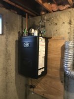
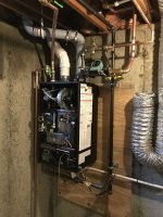
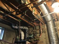
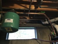
Installers are done for now. They were reusing old transformer for zone valves which we found out can't work and you have to have a taco controller so that will be finished tomorrow. Here's pictures so fAr. Keeping original zone valves. Please be honest with what you think but so far it sounds like the circ is prob best on supply side instead of return. They were able to get it to run if they jump the TT connections. I did hear what sounds like a tiny bit of bubbles in the circ. They said the hivent will release the air and should go away. Could it be because there's not 12 inches of straight pipe before the circ?
 

Attachments

  • IMG_3039.JPG
    IMG_3039.JPG
    105.2 KB · Views: 446
  • IMG_3036.JPG
    IMG_3036.JPG
    105.9 KB · Views: 411
  • IMG_3037.JPG
    IMG_3037.JPG
    64.6 KB · Views: 418
  • IMG_3042.JPG
    IMG_3042.JPG
    92.5 KB · Views: 380
Last edited:

DR-DEATH

Member
Messages
72
Reaction score
0
Points
6
Location
New Hampshire
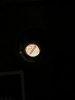
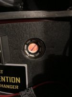
Few more questions: in the manual it says check that the flame is blue. When it's burning all I see is bright orange. Attached is a photo. They have not done a combustion test on it yet and I'm not sure they are planning too. What color is your flame Rob?

Additionally I noticed what seems to be an electrics noise coming from the main board. It's like a er er er noise. Not very loud but there. Does yours do that as well?

While running, the outdoor reset set the low temp at 84 and high temp at 120 something. It's only around (55f out) I watched the temp rise to 122 or so and then the boiler started making like crackeling noises. Sounded like boiling water. Is that normal to hear as well? Anyways sorry for posting so much but I want to make sure everything is good to go.
 

Attachments

  • IMG_3049.JPG
    IMG_3049.JPG
    17.2 KB · Views: 395
  • IMG_3047.JPG
    IMG_3047.JPG
    58.1 KB · Views: 381

Dana

In the trades
Messages
7,889
Reaction score
509
Points
113
Location
01609
Ideally the expansion tank would be on the input side of the pump (as in the NY_Rob's schematic in the previous post), not on the opposite side of the boiler altogether! What you have is the pump driving toward the boiler (which can be fine), with the expansion tank on the opposite side. It's a low pumping-head boiler, so this is effectively pumping toward the expansion tank, which is the opposite of what you want to do.

Putting the expansion tank on the input side of the pump (with the requisite amount of straight pipe) reduces impeller cavitation, which is both a noise and pump longevity issue, among other things.
 

Dana

In the trades
Messages
7,889
Reaction score
509
Points
113
Location
01609
If you're hearing sizzle & pop from the heat exchanger it's usually a symptom of low system pressure.
 
Top