Troubleshooting Dead Outlets in Detached Workshop

Users who are viewing this thread

LarryLeveen

Member
Messages
92
Reaction score
2
Points
6
Location
Washington
I moved into a house with a great detached workshop, except that several AC receptacles don't work:

- one outside GFCI receptacle does not work, and neither the test nor reset buttons appear to function even when pressed firmly
- four (of the eight) inside receptacles along two adjacent walls do not work -- the other four, along the other two adjacent walls work
- an analog multimeter shows good voltage (120v) for the working outlets, no voltage in most of the non-working outlets, and ~4.0 volts in the farthest bad outlet. It had only two wires (plus ground) connecting to it, and not four, which I thought meant that it is the last in a series for that circuit.

Other details:

- at the electrical service panel in the house, there two breakers serve the shop -- they are joined together with a bridge so that they actuate together and each is labeled "50"

- are three switches on the inside of the workshop near the door -- two next to each other control the overhead fluorescent light fixtures and work fine -- but it is not apparent what the third switch, which is separate, does (or is supposed to do). It is located near, but on the opposite side of the wall from the GFCI I mentioned above

I turned off the power at the panel by flipping the double breakers, verified that there was no voltage on all outlets, and then opened up the bad ones to look for loose wires. The one with a low voltage had a loose black wire mounted at the stab-in connector (there were no silver/brass screw terminals). I pulled it out, trimmed it down a bit and remounted it. The other bad outlets had no apparent wiring problems (but I might have missed something since I am out of my element). I also pulled out the lone switch and noticed that the insulation on the white wire was a little cracked. I trimmed it down to eliminate that bad section and remounted the wire on the switch.

Aside, I realize now that I did NOT check the wiring in the last _working_ outlet -- which is next to the non-working outlet with the low voltage.

I need help in troubleshooting the non-working outlets. Seems like it could be that:

- the GFCI receptacle is bad and is preventing the receptacles that follow it in series from working.
- the GFCI alone is switched
- the bad indoor receptacles are switched

Thoughts? Recommendations? I think tomorrow I'm gonna pick up an outlet tester to help me determine if things are wired correctly or not as I can use that help (being less experienced).
 

Jadnashua

Retired Defense Industry Engineer xxx
Messages
32,770
Reaction score
1,190
Points
113
Location
New England
The GFCI receptacle should be near the first in line, assuming it is protecting the rest of the receptacles in the garage workshop. IF it isn't, that may mean that there is another one somewhere.

When they use a 50A, double breaker, that often implies a subpanel is being fed, as technically, a 50A breaker should have wire that can handle 50A connected to each device it protects unless there's a subpanel somewhere in between, and then it becomes a 15 or 20A branch circuit. DO you have a subpanel somewhere feeding the garage electrical? If so, it sounds like one or more breaker is tripped.

On a receptacle where it had a loose wire. Assuming it was inserted properly and was the proper gauge for that device, and it was loose...that often can mean that it was overloaded, and the spring tension has become loose...it may not be providing any feed-through. I'd replace that one, at the least with a new receptacle. I prefer one with screw terminals, but also one that you can put the wire in from the back, but then the screw clamps down on it rather than under the screw head, if that makes sense.

Generally, you have two ways to trace things to find the break...follow it to the last place that has power and has both an in and out cables...the break is between that thing and the next. Or, you can buy a signal tracer device. One end gets attached at the breaker panel, then there is a 'sniffer' device that will indicate when there is a signal and you can tell where it stops. I had a similar situation...had to find where the wire was bad (in my case, the GFCI was tripping)...when one lead was disconnected from a receptacle that fed things through, the GFCI started to work...rather than finding the issue (maybe a screw or nail through the line), I replaced that section, and everything has worked fine since.
 

Reach4

Well-Known Member
Messages
38,848
Reaction score
4,427
Points
113
Location
IL
Aside, I realize now that I did NOT check the wiring in the last _working_ outlet -- which is next to the non-working outlet with the low voltage.
Those are the two boxes you want to concentrate on, and the box you did not check would seem to be most likely the location of the problem. I would suspect
  • the connection for the wire feeding power from that working outlet
  • a wire between those
  • a connection from the wires to that last outlet.
With the outlet closed up, and if your meter probes are small enough, measure the voltage between the smaller flat blade hole of the non-working receptical (should be hot) and the ground terminal. If that shows 120VAC, look for a problem with the white wire from the nearer good outlet.

- the GFCI receptacle is bad and is preventing the receptacles that follow it in series from working.
- the GFCI alone is switched
I don't think it could be either of those things. If I read correctly, there is only one GFCI outlet, and it feeds more outlets.
- the bad indoor receptacles are switched
That seems unlikely.
 
Last edited:

LarryLeveen

Member
Messages
92
Reaction score
2
Points
6
Location
Washington
Those are the two boxes you want to concentrate on, and the box you did not check would seem to be most likely the location of the problem. I would suspect
  • the connection for the wire feeding power from that working outlet
  • a wire between those
  • a connection from the wires to that last outlet.
With the outlet closed up, and if your meter probes are small enough, measure the voltage between the smaller flat blade hole of the non-working receptical (should be hot) and the ground terminal. If that shows 120VAC, look for a problem with the white wire from the nearer good outlet.


I don't think it could be either of those things. If I read correctly, there is only one GFCI outlet, and it feeds more outlets.

That seems unlikely.

Doh! I forgot to mention a few things (it was late):

- there is no sub-panel in the workshop.

- the multimeter did indeed show 120v between the hot and ground on the low voltage receptical.

- there are three external lights on the workshop -- one, controlled by a switch in the house, works. I can't tell if the other two work (motion sensor fixtures). One is situated near (but outside) the non-working outlet.

- there are mice in the walls of the workshop -- of course

- the GFCI outlet is within one foot of a oval junction box where the power lines come up through a pipe from the ground.

I'll pull the last good outlet and see if it has two wires or four and check their connections.
 
Last edited:

Jadnashua

Retired Defense Industry Engineer xxx
Messages
32,770
Reaction score
1,190
Points
113
Location
New England
This may or may not help in the future...my preference when daisy chaining power through a box to another with a receptacle, is to NOT use the receptacle's contacts for the connections. I add a pigtail to go there, and combine it with the leads coming in/out. I think it makes it easier, as then there are only three wires on the receptacle (L, N, G) verses two pairs of them. I think in the end, you then have less likelihood of problems as well. IMHO, it's easier to get a good connection with wire nuts than it is to screw all of those stiff wires onto the receptacle.
 

LarryLeveen

Member
Messages
92
Reaction score
2
Points
6
Location
Washington
Well, indeed checking that adjacent good outlet yielded a loose wire. I replaced that crappy stab-in-only receptacle with a screw-terminal type. Now the low voltage recepticle has a good voltage. However, the other three outlets still don't work. I bought enough receptacles to replace them too, but have yet to install them. Perhaps they all need replacing in order to fix the problem inside. Then there is still the GFCI outside that doesn't work. I would be surprised if the GFCI was "after" those outlets.
 

Jadnashua

Retired Defense Industry Engineer xxx
Messages
32,770
Reaction score
1,190
Points
113
Location
New England
On the GFCI that doesn't work...can you press the reset in, and if so, does it stay in?
 

WorthFlorida

Clinical Trail on a Cancer Drug Started 1/31/24. ☹
Messages
5,754
Solutions
1
Reaction score
993
Points
113
Location
Orlando, Florida
There has to be a subpanel, anything on the outside of the garage? A two pole (220v) 50 amp breaker needs to be an 8 gauge wire. Open your panel at the home and check the wire size. At each receptacle or wall switches it will be either 14 gauge (15 amp breaker) or 12 gauge (20 amp breaker). I first track down this subpanel unless one of these boxes has a 8 ga. to 12 ga. wire nut connection. If there is that's bad.

GFCI that are outdoors can fail more often than not due to the dampness and temperature swings. But first check if there is voltage at the GFCI screw terminals. If there is the GFCI is bad. Since all of these outlets and switches are essentially outdoors and in unheated garages, shy away from using the stab-in connection. You're better off with the wire wrapped around the screw terminals. If you use power tools, these inductive motors that takes a lot if current, i.e. 10 amp circular saw, there will be less voltage drop across the connection. Older outlets allowed both 12 and 14 gauge wire to fit but it was found to be problematic for 12 gauge. Now all outlets are 14 gauge size only. Large current loads were burning up the outlets, rare but it did happen; more often with a large voltage drop such as running a window air conditioner at an outlet that was the end of a daisy chain of outlets.
 

Reach4

Well-Known Member
Messages
38,848
Reaction score
4,427
Points
113
Location
IL
No. When I push in the reset, it does not stay in. Also, when I push the test button, nothing happens either.
I think you are saying that the reset button sticks out.

I suspect moisture got into the outlet, and causes the trip. Try to improve the sealing and replace the outlet. You could try baking that outlet at 160 for a few hours, but replacing the outlet would be simpler.
 

WorthFlorida

Clinical Trail on a Cancer Drug Started 1/31/24. ☹
Messages
5,754
Solutions
1
Reaction score
993
Points
113
Location
Orlando, Florida
A GFCI without power the reset and the test buttons will do nothing. With power you'll feel the reset button click and the test button will pop the test button. A bad GFCI with power will fail the same as no power, this is why voltage at the terminals must be checked.
 

Jadnashua

Retired Defense Industry Engineer xxx
Messages
32,770
Reaction score
1,190
Points
113
Location
New England
FWIW, a circuit breaker in a panel is sized to protect the wire, and if you have a 50A breaker, and are using it with smaller wire, you have a definite safety and code problem, which is why we have been saying, there must be a subpanel somewhere in between.
 

LarryLeveen

Member
Messages
92
Reaction score
2
Points
6
Location
Washington
FWIW, a circuit breaker in a panel is sized to protect the wire, and if you have a 50A breaker, and are using it with smaller wire, you have a definite safety and code problem, which is why we have been saying, there must be a subpanel somewhere in between.

First off, thank you all for your responses, I really appreciate them. Keep the ideas coming.

To my knowledge (observation) there is no sub-panel at the workshop. The double 50a + 50a breaker in the house, controls power to the shop. A pipe comes out of the ground near the workshop door. Above it is a GFCI that I replaced, though this did not help -- the test & reset buttons don't do anything.

IMG_5797.jpg


Closeup of the lower box:
IMG_5798.jpg


Just inside is the mystery switch (see below). I think it is a 3-way switch being used as a 2-way as there is a third terminal that had no wire hooked up to it (the two hot wires each had a terminal on one side of the switch, and the ground wire had its own green terminal). The two neutrals were wire nutted together without any pigtail.

IMG_5795.jpg


I think it was a bit kooky to have a pigtail hot wire for just one single wire. I think I removed that to make more space in the box.

IMG_5796.jpg


Is that a 3-way switch?

IMG_5799.jpg
 

Reach4

Well-Known Member
Messages
38,848
Reaction score
4,427
Points
113
Location
IL
  1. An outdoor outlet, especially a GFCI outlet, should have a weatherproof cover.
  2. The reset button on the GFCI in the photo is not sticking out. #8 seemed to imply that the button stuck out, and I tried to confirm that in #10.
  3. That bottom box needs a weatherproof cover too.
 

WorthFlorida

Clinical Trail on a Cancer Drug Started 1/31/24. ☹
Messages
5,754
Solutions
1
Reaction score
993
Points
113
Location
Orlando, Florida
The pipe out of the ground, does that come from the house? I cannot tell for sure if there is a black wire but it does appear to be one. The red will be the hot, therefore there does seem to be a 220v.
If that pipe out of the ground is from the house, it's fed with 12 gauge wire.
The switch does look like a three way switch because there is no ON/OFF on the toggle.
Did you look at the 50 amp breaker wire size? From the main panel can you follow the wire where it leaves the house to the garage?
 
Messages
65
Reaction score
3
Points
8
Location
Forest Grove, OR
I would replace that GFCI. They do go bad, especially likely if mounted outdoors without a weather tight cover.

Also, as others have said, there really probably is a subpanel somewhere that you can't find. There's no legal way to feed 15 or 20A circuits off a 50A two pole breaker without a subpanel. There have to be 20A or 15A breakers somewhere feeding those circuits, and if there aren't I'd turn that 50A breaker off until I got it fixed. It's a major fire and safety hazard. It is unlikely that a 50A breaker will trip before the wire glows red hot, even with a dead short on a long enough run of #12 or #14 wire, and 50A is too much current for a #12 ground wire to carry to prevent fatal shock if you are touching the box when it faults.
 

Jadnashua

Retired Defense Industry Engineer xxx
Messages
32,770
Reaction score
1,190
Points
113
Location
New England
Not counting the ground connection, a 3-way switch will have three terminals for hot wires to attach. So, with a grounded version, there should be four different places to attach a wire.
 

LarryLeveen

Member
Messages
92
Reaction score
2
Points
6
Location
Washington
Thanks. I agree that there is something really odd going on here, and I was just about done investigating due to the potential safety issues brought up here. One last idea -- behind the freezer! NOPE. Nothing there, but then... what's up with that dorky cabinet mounted on the wall near the three indoor switches (and also the external stuff pictured above)?
IMG_5806.jpg


It was a struggle to get it off as it wasn't screwed into anything structural, but then:
IMG_5807.jpg
IMG_5802.jpg


Well, lookee here! And two popped breakers! Resetting them resulted in the dead outlets now working (and wired properly according to my outlet tester), and the GFCI now being able to be reset and tested (and the outlet tester saying it is wired right).

I had already learned that the outdoor GFCI needs a special cover (not just any cover) to comply with code. The current cover has a foam gasket which looked to me like a draft blocker (kinda janky at that), and the pipe from the ground has a cover, though it's gasket looks pretty shot from sun/weather. Is a proper cover an easy DIY install?

Wow, thanks guys for being so insistent that there must/should be a subpanel! I was right about to give up and call in an electrician to figure out what the heck was going on. Should I still have one come in? If so what should I ask them?

I have a new question, though: On investigating the various outlets, I have seen that on several of the receptacle boxes, the screw threads are stripped, so the screws cannot properly hold the receptacle in the box (one usually does so that the receptacle is tilted up or down). What is a good/decent fix short of replacing the box which seems like a pain in the butt?

Thanks again!!!
 

Reach4

Well-Known Member
Messages
38,848
Reaction score
4,427
Points
113
Location
IL
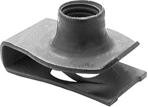
What is a good/decent fix short of replacing the box which seems like a pain in the butt?
I would try to put a 6-32 U-nut over the existing stripped tab. If I could not do that, I might try drilling and tapping to use a #8 screw.


0162869_hr1c.jpg
 

Jadnashua

Retired Defense Industry Engineer xxx
Messages
32,770
Reaction score
1,190
Points
113
Location
New England
FWIW, I don't think that your subpanel would pass a current inspection...I don't remember the numbers, but there must be clearance on both sides, above, and in front of the panel...sticking a shelf over it, certainly isn't to code, either. The metal cover is to help prevent a spark from igniting something and for safety!

Installing a waterproof outlet cover is a simple job...take the existing cover off, screw the new one on. There are lots of different designs.
 
Top
Hey, wait a minute.

This is awkward, but...

It looks like you're using an ad blocker. We get it, but (1) terrylove.com can't live without ads, and (2) ad blockers can cause issues with videos and comments. If you'd like to support the site, please allow ads.

If any particular ad is your REASON for blocking ads, please let us know. We might be able to do something about it. Thanks.
I've Disabled AdBlock    No Thanks