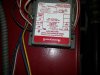
OK, so looking back there a bit more, it would appear that I'm measuring from the wrong terminals. Not sure what the box is posted above, but took another pic of what I think is relevant. So on the below picture, I get 24v to ground from the blue and black wires, and 24v from blue to yellow. Nothing from yellow to ground. The blue and yellow connect to the red and white tstat wires, respectively. On the upper left of the pic, the terminals are listed as "burner" (B1/B2) connected to blue and white wires. Beneath that is "circulator" (C1/C2, red/yellow). To the left of that is my 120v line input. Not sure what that is above the relay, or where the blue/red wires lead--looks like a timer switch or something?
So...
I'm guessing that the blue wire is one terminal of the secondary. The yellow wire (connected to W) is the back side of the relay (which is bottom middle of the pic). Unless in use, that wire should be isolated. Correct so far? The black wire on the right is connected to a terminal marked "W" under the tag.
Further guessing that the first pic I posted is a power distribution box. Red wire on the left is coming from what appear to be some temperature limit fuses/switches. White goes to the B(urner)2 terminal in the transformer box.
Ok, so that first pic is fed by 24v and feeds the gas valves and ignitor. It should get power directly from the transformer, right? That would be the red wire? And the white goes to the second secondary terminal? One of them must be connected to the W wire from the stat?
In the transformer box, one side of the relay should be fed by the transformer (which wire?). The other side should be the W wire from the stat (yellow in the box). The stat connects the red (blue in the box) wire to the white wire, trips the relay, and supplies 120vac to the circulator.
So putting it all together, my understanding is:
Line voltage to transformer primary and relay. Transformer secondary (blue wire) goes to R in stat, which connects to W, which powers relay. The other side of the relay is connected to the other side of the transformer secondary (which wire, the black one on the right?). Somehow the red and white wires on the box in the first pic are energized when there's a call for heat, and then each is connected to one of the secondary terminals (?).
Sorry for the long post, just trying to learn something here
")