Killacam311
New Member
Hi,
I have oil for my furnace and my boiler which supplies hot water.
I was doing a bit of a remodel and accidentally moved my oil supply/return lines slightly. In doing so, I think I created air issues in the lines because my hot water stopped working. I spent several hours rigging up the old lines and bleeding them to get the system working again for a few days until I could get new lines. I needed to move the lines anyway as part of my basement remodel, so it's not a huge "accident".
I now have my new lines, which is why I am now here to ask my questions. Appreciate any help!
I am uploading pictures what the current system looks like. There are text added to the pictures to help reference my questions below.
Questions:
1. Is the old "design" of this system sufficient enough to recreate? I plan to replace the lines with coated 3/8" OD copper tubing. My plan is to have the supply/return lines come out of the top of the tank, bend downward toward the floor, then take a general downhill trajectory to the furnace and boiler. I will make sure the lines are about 2 inches off the bottom of the inside of the tank so they don't pick up sludge. I will skin the protective coating off the copper tubing before inserting into the tank, and will use a standard compression fitting with pipe dope to hold the supply/return lines in place at the tank connection. I've heard this method is ok and will add a siphon effect coming out of the tank. Issues?
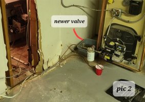
2. I am likely going to replace most of the connectors. I am going to used flared connectors, which most currently are. Generally, is it ok to reuse the more "robust" connectors, like the valves, if they are not clearly damaged? Its not a money thing, it's a time issue - its hard to get these valve connectors in my area.
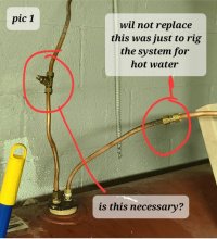
3. Do you see any unnecessary connectors in the pictures? Specifically, is the "tee" connector on the return line (above the tank) necessary (Pic 1)? Is that for siphoning? Not sure it's purpose, but it has what appears to be a bleeder screw on it. Note that the other connector in Pic 1 will not be replaced - I needed it to rig up the system to work for hot water until my new lines were shipped in. I won't add that back on the news lines... but should I add the tee back?
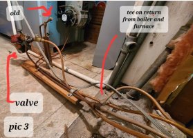
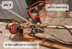
4. Is the maze in Pic 3 and Pic 4 designed ok? Is the tee on the return lines ok (Pic 3)? Is the connection system in Pic 4 ok? Looks like there is a shut-off before the split, and another shutoff at the furnace oil filter. There is also a separate shut off at the boiler oil filter.
Generally, I will clean up the lines so they are organized and secured appropriately.
Thanks for any advice you can give.
I have oil for my furnace and my boiler which supplies hot water.
I was doing a bit of a remodel and accidentally moved my oil supply/return lines slightly. In doing so, I think I created air issues in the lines because my hot water stopped working. I spent several hours rigging up the old lines and bleeding them to get the system working again for a few days until I could get new lines. I needed to move the lines anyway as part of my basement remodel, so it's not a huge "accident".
I now have my new lines, which is why I am now here to ask my questions. Appreciate any help!
I am uploading pictures what the current system looks like. There are text added to the pictures to help reference my questions below.
Questions:
1. Is the old "design" of this system sufficient enough to recreate? I plan to replace the lines with coated 3/8" OD copper tubing. My plan is to have the supply/return lines come out of the top of the tank, bend downward toward the floor, then take a general downhill trajectory to the furnace and boiler. I will make sure the lines are about 2 inches off the bottom of the inside of the tank so they don't pick up sludge. I will skin the protective coating off the copper tubing before inserting into the tank, and will use a standard compression fitting with pipe dope to hold the supply/return lines in place at the tank connection. I've heard this method is ok and will add a siphon effect coming out of the tank. Issues?
2. I am likely going to replace most of the connectors. I am going to used flared connectors, which most currently are. Generally, is it ok to reuse the more "robust" connectors, like the valves, if they are not clearly damaged? Its not a money thing, it's a time issue - its hard to get these valve connectors in my area.
3. Do you see any unnecessary connectors in the pictures? Specifically, is the "tee" connector on the return line (above the tank) necessary (Pic 1)? Is that for siphoning? Not sure it's purpose, but it has what appears to be a bleeder screw on it. Note that the other connector in Pic 1 will not be replaced - I needed it to rig up the system to work for hot water until my new lines were shipped in. I won't add that back on the news lines... but should I add the tee back?
4. Is the maze in Pic 3 and Pic 4 designed ok? Is the tee on the return lines ok (Pic 3)? Is the connection system in Pic 4 ok? Looks like there is a shut-off before the split, and another shutoff at the furnace oil filter. There is also a separate shut off at the boiler oil filter.
Generally, I will clean up the lines so they are organized and secured appropriately.
Thanks for any advice you can give.