New Boiler Manifold Plumbing problems

Users who are viewing this thread

Rob Bemis

New Member
Messages
6
Reaction score
0
Points
1
Location
Boston
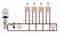
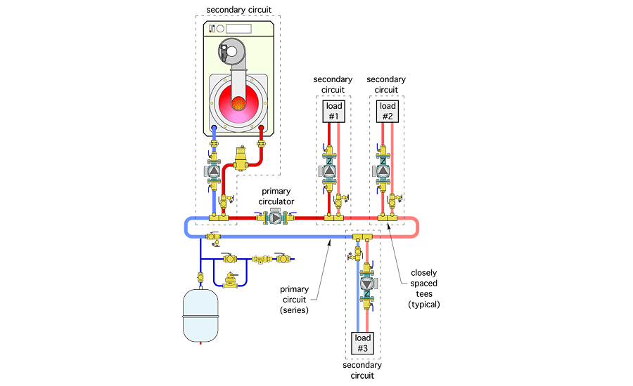
Hi everyone, I completely replaced the heating system in a home I purchased last year, and am having some trouble when multiple zones are calling for heat. Its a 3 zone system, and the order of the zone take offs from the primary loop is 1,2,3, with 1 being basement/laundry, 2 is living area, and 3 is sleeping areas. If zone 1 calls for heat, then all of the hot water is being taken up by that zone, and same applies going down the line. This causes any zone further down the line than any zone calling for heat to get lower temp water, and not really heating.

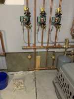
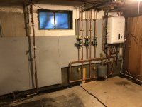
The zone controller does have a priority capability to shut down zones 1&2 if zone 3 is calling for heat, but on really cold days, zone 3 may call for heat for extended periods leaving the other 2 zones shut down if I use the priority function, so not an optimal solution. I'm wondering if the primary loop design is wrong, and not allowing the zones to share the water sufficiently between the 3 zones, or if something else is going on. An image of the install is attached.
 

Attachments

  • plumbing.jpg
    plumbing.jpg
    83.7 KB · Views: 5,076
Last edited:

Dana

In the trades
Messages
7,889
Reaction score
509
Points
113
Location
01609
I see the supply manifold connected directly to the return manifold on the left side. The only path between them SHOULD be the returns from radiation. Cut and cap the manifolds getting rid of that big U, making it into separate supply and return manifolds. (Was this installed by a pro?)

index.php


I see only two returns tapping in to the return side, but three supplies?

Are those circulator pumps all 007e or something else?

Are the integral check valves installed on those pumps?

How much total plumbing is there on each zone (including the radiation itself)?


Are you operating the NCB at fixed output temperature, or are you using the outdoor sensor and programming "K-factor" curves? (Which model NCB is it?)
 
Last edited:

Rob Bemis

New Member
Messages
6
Reaction score
0
Points
1
Location
Boston
Hi Dana, and thanks for responding. This was installed by a "Pro", but i'm no longer confident that he knew 100% what he was doing. Zone 1 is pre-existing slant fin, so you will see the return from that zone coming in from the white pex at the bottom right of the photo. The other two zones are hydronic loops through new fan coils (you see them penetrating the ceiling going up to the attic (This is a split level with vented attics).

Boiler is an NCB-240E

All 007e circulator pumps, but I'm not sure if the Integral check valves were installed.

Zone 1 probably has 150' of plumbing, but only about 40' of radiation
Zone 2 has about 60' of pex to the fan coil
Zone 3 has about 100' of pex to the fan coil

The system is running in fixed output temp mode. Also, running on Propane thanks to the National Grid strike, and its costing me a fortune!
 

Dana

In the trades
Messages
7,889
Reaction score
509
Points
113
Location
01609
With the fan coils you're pretty much required to run at fixed temp to keep the exit-air temperatures reasonable at the registers. But you can probably lower that fixed temp to 125F or so and still heat the place once you fix the stupid-attack on the direct bridge between the intake and return manifolds.

With that direct bridge a the left of the manifolds in place about half the return water is going through that connection, so when the zone pump nearest the NCB is running the next zone over is getting diluted heavily with the cooler return water from the first zone. If you break that connection all of the water going to those other pumps has to go through the hydraulic separator (the mini-manifold with the tees) at the boiler, where it will be heated before getting the pump, the way it SHOULD be.

If the check valves aren't in place, when one zone is running it will induce backflow through the other zones, which may or may not be a problem on your system. If the air handler blowers are controlled by an aquastat sensing the water temp, it may turn on intermittently sending tepid air into the zone even when the zone's thermostat isn't calling for heat. If that isn't happening already, it's not likely to happen, but it's useful to know where the water is flowing. Back flowing water though the inactive pumps will also dilute the entering water temp at the active pump to a lower temp, but there is enough plumbing resistance on all of those runs that it won't become an overwhelming factor, the way the illegitimate connection between the manifolds is.

The minimum fire output of the NCB 240e is ~17000 BTU/hr at condensing temps. When just zone 1 is calling for heat with only 40' of baseboard that's a ratio of 17000/40= 425 BTU/hr per foot. At an average water temperature less than 155-160F the boiler is going to cycle on/off, and and at an average water temp of 120F (necessary to hit anywhere near 95% efficiency) the baseboard won't even be emitting half the min-fire output of the boiler, and without some boiler setup programming &/or design fixes it could even short cycle pretty badly. But we can address that once the gross error on the manifold is fixed (since there's no way to really do that before the manifolds are separated.)

BTW: Is this a natural gas version of the NCB running on propane with some hacks to somehow make it work? I've never looked into what it takes to do the conversion on one of those from gas to propane or conversely, but it's much more than just flipping DIP switches on the control boards!
 

Rob Bemis

New Member
Messages
6
Reaction score
0
Points
1
Location
Boston
This is a natural gas version that was converted to LP, ostensibly by replacing the gas orifice to the LP version.

Lowest I've been able to get the supply temp and maintain adequate heat is about 140.

I also thought the manifold setup was strange, but in my research, I've seen many diagrams showing this same exact configuration (See attached).

Are you in Worcester? Feel like a trip to Newton? ;)
 

Attachments

  • ControlsHPACMAG.jpg
    ControlsHPACMAG.jpg
    23.3 KB · Views: 2,023

Dana

In the trades
Messages
7,889
Reaction score
509
Points
113
Location
01609
OK, where is the pressure bypass valve on your system?

index.php


Your system isn't running with a single pump with zone valves that needs a pressure relief path for when the valves close when the pump is still spinning, and I don't see a pressure bypass valve on your manifold connection. That pressure bypass valve is only open there is a big enough pressure difference between the supply and return manifolds to open it up. Without the valve it's free-flowing all the time.

Note, the label Primary Pump in that drawing is mis-using the term. The pump driving toward the boiler with the closely spaced tees is what most hydronic designers would call the primary pump (driving the primary loop). The other pump is usually called the radiation pump or secondary pump (driving the secondary loop). Your system is also plumbed primary/secondary, but your primary pump is located inside the NCB.

Without the dilution of the return water mixing you should be able to crank the temp down at least 10F, maybe 20F and still heat the place, depending on the actual zone loads and the specific air handlers. (Got model numbers?)

I live in Worcester, work in Burlington, but it's a long enough commute as it is without side trips to Newton...

[edited to add]

The "Primary Pump" would only be correctly named in the diagram if the zones all had their own "secondary pump" sipping from the loop going off on closely spaced tees, rather than zone valves with the returns on a remote section of pipe on the loop. They have all sorts of names for multi-parallel/series blah blah topologies that only a hydronic design instructor could love. But suffice to say you would at the very least need yet another pump drive that loop and some balancing valves to make that topology work in your case:
1-PM-oct-2016-fig.png

The more direct (and totally legitimate) approach is to keep it simple, break the loop into separate supply and return manifolds.
 
Last edited:

Rob Bemis

New Member
Messages
6
Reaction score
0
Points
1
Location
Boston
Got ya, sorry, I thought you might be a contractor. I also don't see the pressure relief valve, but is adding one a better/more appropriate fix than just capping the ends of the manifold off? Is that protection provided by another component elsewhere in my install, or did he just miss that? Is there no mixing of supply and return water at the T's closest to the boiler? Why is the loop bridged there?


Dana

In the trades
Messages
7,889
Reaction score
509
Points
113
Location
01609
Got ya, sorry, I thought you might be a contractor. I also don't see the pressure relief valve, but is adding one a better/more appropriate fix than just capping the ends of the manifold off? Is that protection provided by another component elsewhere in my install, or did he just miss that? Is there no mixing of supply and return water at the T's closest to the boiler? Why is the loop bridged there?

No, because you don't have any zone valves, and you still don't have a pump driving what would be the "Primary Circulation Loop".

The boiler supply is indeed mixed with the return water at the hydraulic separator (the tees just below the boiler in your system), and yes, that lowers the temperature headed toward the supply manifold. But it's being mixed with the boiler output before going down the supply manifold. With the loop on the left end connecting the manifold something like half the return water is bypassing the boiler entirely by flowing through that end loop without benefit of being heated. That's the first 90% or more of your problem here- a large fraction of the return water (maybe even most of it) is back flowing toward the supply loop completely bypassing the boiler. You never want to re-send return water out the supply without first getting some heat from the boiler.

We'll be able to see what the next 90% of the problem is only after you've fixed the first 90% of the problem.

The hydraulic separator tees are needed at the boiler because the water tube heat exchanger inside NCB can't handle the much higher flows used by the radiation/air-handlers, and it needs to maintain it's minimum flow through the boiler independent of the state of the radiation pump operation. By placing the return and output tees very close to one another it minimizes the interaction between the boiler (primary, on this system) pump flow and the radiation flow. As more zones call for heat the flow through the fat pipe goes up, but the flow through the boiler is barely affected. They term they use for this is "hydraulic separation of flows". There are other types of hydraulic separator devices, and they can be build up from fittings, but the pre-engineered pre-plumbed tee manifold designed by Navien is suitable for almost all residential heating applications and it bolts right on, a time saver for the installer.
 

Dana

In the trades
Messages
7,889
Reaction score
509
Points
113
Location
01609
Without enough information to do even the napkin math on it I'm guessing that with 140F out of the boiler into the hydraulic separator and the illegitimate un-pumped loop tying the manifolds together sending return water back to the supply manifold side, with just one air handler running the temperature of the water being sent to that air handler is about 120F-125F. Breaking the illegitimate connection it would be sending 130-135F water out to the air handler with just one zone running, and still over 125F to all zones with all zones running.

There is NO legitimate reason to have the manifolds connected at the far end.
 

Rob Bemis

New Member
Messages
6
Reaction score
0
Points
1
Location
Boston
Dana, Thanks so much for your patience, and all the help. You are a gentleman and a scholar. Will report back when I make these changes.

Rob
 

Rob Bemis

New Member
Messages
6
Reaction score
0
Points
1
Location
Boston
Hi Dana/Everyone, well I cut the loop off the manifold, and all zones are now getting adequate hot water even when all zones are calling for heat. Thank you to Dana, as he quickly diagnosed the problem, and gave excellent advise. He’s a godsend to those of us trying to recover from shoddy work done by incompetent contractors. On to the next project!
 

Attachments

  • 5B925973-3FF4-47AF-B5E1-D14DCF180236.jpeg
    5B925973-3FF4-47AF-B5E1-D14DCF180236.jpeg
    84.5 KB · Views: 2,016

Dana

In the trades
Messages
7,889
Reaction score
509
Points
113
Location
01609
Hi Dana/Everyone, well I cut the loop off the manifold, and all zones are now getting adequate hot water even when all zones are calling for heat. Thank you to Dana, as he quickly diagnosed the problem, and gave excellent advise. He’s a godsend to those of us trying to recover from shoddy work done by incompetent contractors. On to the next project!

You're not QUITE done here! Remember this was just the first 90% of the problem- the next 90% (there's always another 90% :) ) is to optimize it for efficiency and comfort.

The first thing to do now is turn the fixed temperature down to where the entering water temperature at the boiler is under 120F and see if it still heats the place, and that the exit air temperatures at the furthest registers are still 100F or higher. This thing won't hit 95% efficiency until the entering water temperature at the boiler hits ~115F or so. But much below that you may end up with a wind-chill effect if the exit air is too tepid. On my own hydro-air zone the entering water temp (EWT) at the coil is 120-125F, and one far register's output is running in the low 90s (it's an antique 1920s house with un-insulated hard-piped ducts) but since it's not in a location where it will ever blow directly on people it's fine.

Once that is all working fine from a comfort and total heat delivery point of view, turn the thermostats on the air handler zones way down, then turn the thermostat on the baseboard zone way up and time the burns. As long as the burn times are at least 3 minutes long and well under 10 burns per hour it's not big deal, but a couple dozen 50 second burns per hour it's going to wear out the boiler and deliver poor efficiency when serving just that zone.

If it's short cycling on the baseboard zone, first take a deep dive reading and re-reading chapter 10 of the manual, until you're sure you know what the different settings and parameters do. Report back here on the boiler's cycling behavior and we'll take it from there. . Tweaking parameters L and M to a wider temperature swing while cycling will increase burn times, but try to keep it in the condensing zone (roughly 130F output) if you can. If it's still short cycling you may need to increase the time-out on parameter H to limit the short-cycling, but taking it too far can inhibit the ability of that zone to be heated.
 

Dana

In the trades
Messages
7,889
Reaction score
509
Points
113
Location
01609
Ive seen a setup like this hefore but they had a pump on the manifold loop

Yeah, and the zones were probably on closely space tees (or should have been) rather than separate supply & return manifolds. There's no point to adding the additional pump (and extra pumping power) to this one. Who knows what the original installer was thinking when building it up this way!?! A poorly copied idea of something they saw work once, perhaps?
 
Top
Hey, wait a minute.

This is awkward, but...

It looks like you're using an ad blocker. We get it, but (1) terrylove.com can't live without ads, and (2) ad blockers can cause issues with videos and comments. If you'd like to support the site, please allow ads.

If any particular ad is your REASON for blocking ads, please let us know. We might be able to do something about it. Thanks.
I've Disabled AdBlock    No Thanks