Equivalent Bladder Tank Size to old Galvanized Tank

Users who are viewing this thread

pyro2

New Member
Messages
5
Reaction score
0
Points
1
Location
Connecticut
Hi All,
What would be the equivalent size Well-X-Trol tank to my current 80 gallon galvanized tank? Its currently 50/70 psi pressure. I need to replace my galvanized tank and wondering what equivalent size would be. According to my home inspection, my pump is 1/2 HP and well had 3 GPM recovery. I have run out trying to water lawn.

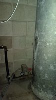
To get me through another week or two, how do I pressurize my current galvanized tank? There is no shrader valves or any way to get air in. It has one ~1.5" capped fitting on the side and one large one on top. Its just a plug. I have an old service contract from previous owner where they say they charged it with 70 psi, but I have no idea how.

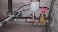
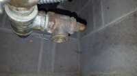
I drained the tank completely and let it fill with atmosphere air, turned water back on, but its still short cycling - 4 or 5 times just to fill a toilet. I assume its leaking around the side fitting since there is slight discoloration, but I was also expecting to see more water leaking. I also noticed someone previously put some sort of gray grease/putty on it, maybe to attempt to plug a leak.
 

Attachments

  • IMG_20170709_100456770 (Small).jpg
    IMG_20170709_100456770 (Small).jpg
    55.6 KB · Views: 1,952

Reach4

Well-Known Member
Messages
38,899
Reaction score
4,436
Points
113
Location
IL
How deep is your pump, and how far is it to water? From that, we could estimate the GPM of the pump. Take the GPM pumped, and multiply by 4. Get a tank with at least that nominal size.

Probably a 44 gallon pressure tank would be a good sized. Maybe 32 would be OK too.

Click Inbox above.
 

Craigpump

In the Trades
Messages
2,436
Reaction score
158
Points
63
Location
Connecticut
You have to put air in the tank to properly balance it, atmospheric pressure won't do it. I've seen guys pressurize galvanized tanks through the boiler drain, of course the tank has to completely drained first.

What are the dimensions of your tank? From there I can tell what size it is and what would be a good size to install.
 

pyro2

New Member
Messages
5
Reaction score
0
Points
1
Location
Connecticut
Inspection report says the well is 200' deep. It say 3 GPM recovery rate for one hour. No mention of water table level. I don't have the original well drill report.

I have no idea how they pressurized this. There is a small threaded drain plug on one of the valves near the sediment filter which maybe can be used? Or maybe on the valve and drain on the tee? Is there some standard valve I can add onto the capped fitting on the side or top?

I was thinking 44 gallon tank as well since I think I have seen a few other houses in my area with approx that size. But I have plenty of room for bigger if needed. Friend down the street just put in 81 gallon which may be oversized. Planning to get the 40/60 pressure switch since I can't seem to find 50/70 at online shop.

Thx for the help!
 

Reach4

Well-Known Member
Messages
38,899
Reaction score
4,436
Points
113
Location
IL
You can adjust the 40/60 up by turning the nut on the big spring.
To raise or lower the cut-in and cut-out settings while keeping the
differential between those two settings constant, adjust the range
nut. The range nut is the 3/8-inch nut that adjusts the larger of
the two springs in Models FSG, FYG, FRG, and Type G Pumptrol
switches.
Turn the range nut clockwise to increase the cut-in pressure and
counter-clockwise to lower the cut-in pressure. Three and a half
revolutions of the range nut will change both the cut-in and
cut-out settings by approximately 10 psi.​
 

Valveman

Cary Austin
Staff member
Messages
14,633
Reaction score
1,304
Points
113
Location
Lubbock, Texas
Website
cyclestopvalves.com
44 gallon tank makes me think you are looking at diaphragm type tanks. Galvanized size would probably be a 42. You don't want to switch from a galv tank to a diaphragm type tank until you figure out if there is a bleeder orifice or two in the well. There should be a check valve going into the tank. Probably it with the pressure switch and gauge attached (bad pic). There should be an extra 1/4 or 1/8 port for a Schrader to add air.
 

pyro2

New Member
Messages
5
Reaction score
0
Points
1
Location
Connecticut
I was able to find the Schrader valve. It was on the bottom side of the tee right under the nipple for the pressure switch. It had a metal cap with the removal tool on the backside which is why I did not recognize it. Apparently this is how valve caps used to be made - and I'm just too young!

I pumped about 30 psi of air while it was (mostly) empty. Probably should have went a little higher, but think its ok. The pump still fills the tank extremely fast (about 5-10 seconds to go from 45 to 70 psi), but it now takes much longer to empty with the kitchen sink running. One think that seems to be nicer on diaphragm tanks is there is a clear instruction how much to charge it. Galvanized it seems everyone has a different answer!

There is a check valve or pressure relief contraption before the pressure switch near the tank. How do I know if there is a bleeder orifice in the well? I assume I need to get down below the 42" frost line to follow the hose into the casing? Maybe not worth the effort and I should keep the galvanized tank.
 

Craigpump

In the Trades
Messages
2,436
Reaction score
158
Points
63
Location
Connecticut
A snifter valve with a cap indicates no bleeder on the drop pipe.

Galvanized tanks aren't all bad, with a bleeder and an AVC, they can be maintanence free (almost) and can help eliminate an H2S smell. Unfortunstely, most galv. tanks have the date on the bottom...

Where in CT.
 

pyro2

New Member
Messages
5
Reaction score
0
Points
1
Location
Connecticut
I just read the snifter valve allows air into the system to drain the hose going to the well? I am unclear how it lets air in with the cap. Perhaps there is a small hole in the cap I did not notice? I read the AVC is installed on the water tank, yet there is no fittings on the tank other than inlet and outlet. The two other ports are capped.

This snifter valve is where I put air into the system and heard it going into the tank. Hopefully that is correct.

PM'd location.
 

Valveman

Cary Austin
Staff member
Messages
14,633
Reaction score
1,304
Points
113
Location
Lubbock, Texas
Website
cyclestopvalves.com
The cap probably just got put on the Schrader because someone didn't know it needed to stay off. When the pump shuts off see if any air is being sucked into the Schrader. If air is being sucked in, then you have a bleeder or a hole down the well. If air is not being sucked into the Schrader, you will need to air it up on a regular basis. it takes lots of air to charge that tank. Basically turn power off to the pump, open a faucet and start adding air. When air starts coming out the faucet, stop adding air, close the faucet, and turn the pump back on.
 

Reach4

Well-Known Member
Messages
38,899
Reaction score
4,436
Points
113
Location
IL
If you have a sniffer valve to admit air, and a drain-back valve in the well and a topside check valve, you would also need an AVC (air volume control). That would have been what that side port in the tank was about. I think that brass that the pressure gauge and pressure switch are screwed into is a check valve.

Speculation: I suspect is that at some point, the drain-back 10 ft down the well got blocked, and no longer drained water. Or it could have been that the check valve no longer blocked water from above, and air did not come into the drain-back valve. Since there was no air, there was not a need to release excess air. The person removed the AVC (maybe it was leaking) and blocked the side port. The user probably just intended to use an air pump periodically until the next well service or until he moved out. So you will do that until you get a new pressure tank.

If you get well service in the future, keep an eye out for that drain-back valve.
 
Last edited:

pyro2

New Member
Messages
5
Reaction score
0
Points
1
Location
Connecticut
Here is a better pic of the incoming side. Where is the check valve in this setup? There is no AVC on the tank. The well pipe is below frost line so I'm thinking there is no automatic air replenish system here. I think it just needs to be manually charged.

Condensation is now allowing me to feel the tank and I can tell there is just over 50% water.
 

Attachments

  • 20170711_213533.jpg
    20170711_213533.jpg
    81.4 KB · Views: 708
  • 20170711_213626.jpg
    20170711_213626.jpg
    49.8 KB · Views: 731

Craigpump

In the Trades
Messages
2,436
Reaction score
158
Points
63
Location
Connecticut
The check valve (control center) here is between the gate valve and T with the pressure relief valve, the pressure switch nipple is screwed into it. The galvanized nipple screwed into the brass check valve will become a problem.

You really want about 1/3 water & 2/3 air.
 
Top
Hey, wait a minute.

This is awkward, but...

It looks like you're using an ad blocker. We get it, but (1) terrylove.com can't live without ads, and (2) ad blockers can cause issues with videos and comments. If you'd like to support the site, please allow ads.

If any particular ad is your REASON for blocking ads, please let us know. We might be able to do something about it. Thanks.
I've Disabled AdBlock    No Thanks