Joseph Skoler
Member
I am in way over my head.
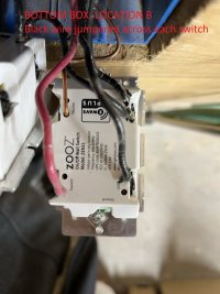
I have a 3-way light switch environment. Lights are overhead LEDs. It was working fine, then I put in a Zooz (Internet/remote controlled, electronic) 3 way switch at one of the switch locations. I keep blowing the Zooz switches (went through 4 of them).
So I disconnected all wires at switch locations A and B to start fresh. I am not certain where each wire goes (which comes from the line, which to the load, etc.). Pretty sure red at each location is traveler, and bare is ground (pretty messed up if it were otherwise).
But I can't explain the voltage readings I'm getting.
Switch location A:
Bare-White: 37 VAC
Green-Black: 128
Green-Red: 49
White-Black: 83
White-Red: 12
Black-Red: 69
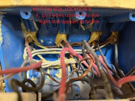
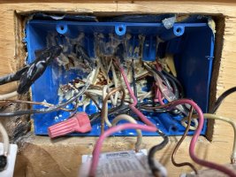
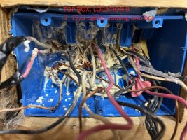
Switch location B:
Green-Black: 0
Green-Red: 49
Green-White: 37
White-Red: 12
White-Black: 37
Red-Black: 49
When I short White to Black at location B, and at location A have red to the traveler terminal of the Zoon, White to the load, bare to neutral and black to line the Zoon functions perfectly (controls the light with the manual switch as well as remotely).
Does anyone know what this could mean?
Thank you.
I have a 3-way light switch environment. Lights are overhead LEDs. It was working fine, then I put in a Zooz (Internet/remote controlled, electronic) 3 way switch at one of the switch locations. I keep blowing the Zooz switches (went through 4 of them).
So I disconnected all wires at switch locations A and B to start fresh. I am not certain where each wire goes (which comes from the line, which to the load, etc.). Pretty sure red at each location is traveler, and bare is ground (pretty messed up if it were otherwise).
But I can't explain the voltage readings I'm getting.
Switch location A:
Bare-White: 37 VAC
Green-Black: 128
Green-Red: 49
White-Black: 83
White-Red: 12
Black-Red: 69
Switch location B:
Green-Black: 0
Green-Red: 49
Green-White: 37
White-Red: 12
White-Black: 37
Red-Black: 49
When I short White to Black at location B, and at location A have red to the traveler terminal of the Zoon, White to the load, bare to neutral and black to line the Zoon functions perfectly (controls the light with the manual switch as well as remotely).
Does anyone know what this could mean?
Thank you.