Well pump failure and electrical question. 1/2hp Goulds pump

Users who are viewing this thread

frankc103

New Member
Messages
5
Reaction score
0
Points
0
Location
S/E Penna
Well here goes. My well was installed in 1986 when house was new! I know that it's a miracle that I've made it this long without any issues, but what started to happen is that the 20amp breaker started tripping. So I pull the well cap off and I notice that the electrical connections that tie the 2 wire line from the pressure switch to the wires coming up from the pump are all melted and the connections are in very poor shape. All the installers did was wire tie the two wires and then put some electrical tape on them. Yeah, it lasted 26 years like that so I guess it wasn't too shotty of work. the pump is 1/2 hp and is set at 135' it's a 220v pump has a amp drawl of 5 amps according to the tag. Anyway they ran 14 gauge wire down to the pump which is ok for a 5 amp draw, but the real question is why would they put it on a 20amp breaker???? I believe what happened is the subjective connections they made living in the damp well casing finally allowed enough moisture into the taped connection that the two wires started arcing between each other and since it was on a 20amp breaker it was more than the 14 gauge wire should have been subjected too. Anyway, I cut the bad splices out got back to some good wire reconnected everything and the pump works again and is only drawing 5 amps as it should.
I obviously am on borrowed time with this pump, and plan to replace it come spring, my real question is isn't 20amp breaker too much for this setup for safety?
 

Valveman

Cary Austin
Staff member
Messages
14,583
Reaction score
1,296
Points
113
Location
Lubbock, Texas
Website
cyclestopvalves.com
The 20 amp breaker is OK. I would have used at least a 15 amp breaker anyway. That old of a motor I don't believe has an overload built into it. So there should be an overload the right size built into the control box. If the control box has ever been changed, you need to make sure you use one that has a built in overload. Probably a loose connection that caused the wires to melt.
 

LLigetfa

DIYer, not in the trades
Messages
7,493
Reaction score
574
Points
113
Location
NW Ontario, Canada
The 5 amp draw is running amps. The locked rotor amps will be much higher, hence the need for 15 amp breaker.

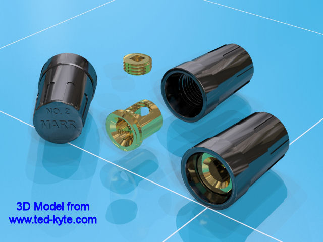
I don't know what you mean by "wire tie the two wires". I like to use Marr connectors without any tape.

Marr%20Connector.jpg
 

Craigpump

In the Trades
Messages
2,436
Reaction score
158
Points
63
Location
Connecticut
He may have meant wire nuts, but I wonder why they didn't just use a splice kit with heat shrink tubing? They are cheap enough and you know they will seal with no problems.
 

frankc103

New Member
Messages
5
Reaction score
0
Points
0
Location
S/E Penna
Ok, a few more observations from today's testing. Here are the specs first: 155' total depth, 135' pump level, running amps consistent at 5.8 amps. 32 gallon bladder tank 28lb set, 30/50 switch, and I can shine a flashlight down the casing and see the water level at about 20' below the surface. Here's what is happening. If I run a spigot at 1/2 to 3/4 open, the system will come on at approx. 30lbs. the pump will run continuously now as long as you leave the spigot open, at actually will go down to 27-28lbs on the gauge. The pump amperage is steady at 5.8 amps, and I can see the water in the casing not go down at all, but the pump won't build any pressure above 28lbs until you shut the spigot, then it will pump up to 50+ lbs and turn off. Before the electrical issue cropped up, the system didn't work like this, the pump could easily overcome one spigot running and still pump the system up to the shutoff level. Is this telling me I'm losing the pump??
 

Cacher_Chick

Test, Don't Guess!
Messages
5,458
Reaction score
213
Points
63
Location
Land of Cheese
You would need to know which pump you have and and compare it to the published pump curve to see if it falls within specs.
 

LLigetfa

DIYer, not in the trades
Messages
7,493
Reaction score
574
Points
113
Location
NW Ontario, Canada
If there is a topside checkvalve, you could have a hole in your downpipe and it manifest the symptoms you describe.
 

LLigetfa

DIYer, not in the trades
Messages
7,493
Reaction score
574
Points
113
Location
NW Ontario, Canada
He may have meant wire nuts, but I wonder why they didn't just use a splice kit with heat shrink tubing?
I suppose a poor job with wire nuts and tape could create a haven for moisture to collect and arc. Wire nuts alone probably would have been better.

Using heatshrink splice on the topside makes it more difficult to pull the pump as you either have to cut the wire or cut the tape holding it to the downpipe. Mind you, I don't think the OP has pulled that pump ever. Over the life of my well, I've pulled my pump probably a dozen times. At first I was using wire nuts but they are not well suited to re-use so I would lose an inch from the leads each time. I switched to the above Marr connectors and tinned the stranded wire so it wouldn't fray.
 

frankc103

New Member
Messages
5
Reaction score
0
Points
0
Location
S/E Penna
I did mean they used std wire nuts. The Only check valve is right on top of the pump down at 135'. This is the same pump for 25+ years, it's not a new pump that I'm not familiar with. It just doesn't seem to be pumping the same volume or pressure of water. Does this happen? I kind of figured once they start going they go! This one isn't running outside it's amperage rating will run continuosly now for as long as you run a water source (I've run it for 30minutes straight) and it doesn't blow the breaker or increase it's amperage draw it just stays right at 28-30lbs and if you open multiple spigot's, there is definetly less volume and pressure than it used to be.
 
Last edited:

LLigetfa

DIYer, not in the trades
Messages
7,493
Reaction score
574
Points
113
Location
NW Ontario, Canada
It could be that the impellers have worn over time but that would not present as a sudden change. My old Goulds pump gradually reduced the GPM over a 12 year time frame due to wear but then I had a sediment problem and it ate a whole lot of sand. It was also pretty heavily caked in manganese and suspect that may have been a contributing factor.
 

Valveman

Cary Austin
Staff member
Messages
14,583
Reaction score
1,296
Points
113
Location
Lubbock, Texas
Website
cyclestopvalves.com
I believe LL is right about the hole in the pipe below the check valve. 5.8 amps means the pump is putting out maximum flow, it is just not making it to the surface. If the pump was worn down, it would not be pulling full load amps.
 

LLigetfa

DIYer, not in the trades
Messages
7,493
Reaction score
574
Points
113
Location
NW Ontario, Canada
I had a neighbor and coworker that had a hole in the pipe. For him though it was gradual. He first noticed that his electric bill was increasing every month. He fought with the PoCo, thinking their meter was to blame. The PoCo changed his meter and it got worse. The hole kept enlarging to the point that the pump was running continuously as it could no longer reach the cut-off pressure. He fought some more... they put in-line one of their diagnostic meters and confirmed he was actually using more electricity. It was only after the pressure dropped ridiculously low because the hole got so big that they determined the cause.
 

frankc103

New Member
Messages
5
Reaction score
0
Points
0
Location
S/E Penna
Just to make sure I'm understanding the message clearly. The only way there could be a leak below the check-valve would be in the pump itself since the check valve is connected directly to the top of the pump unless as you suggest there is a hole or leak at the threads where this valve connects directly to the pump top. I didn't notice anything that looked like a hole there. I do appreciate your opinions and believe at this point, I'll attempt to limp thru the winter and if I make it to spring I'll just put a new pump/valve/switch in and see what happens. I'd say after 26 years on this setup it doesn't owe me anything anymore. The real question is will I make it to Spring!
 

Craigpump

In the Trades
Messages
2,436
Reaction score
158
Points
63
Location
Connecticut
@LL I'm trying to figure out what is so difficult about splicing wire with shrink kits or cutting the tape that holds the wire to the drop pipe.

@Frank, while I appreciate your wanting to get as much use as possible out of your old pump, Murphy's Law states that it will quit at the most inopportune time, Christmas Eve, Christmas Day, New Years Eve, New Years Day.....
 

kenwalkerconst

New Member
Messages
9
Reaction score
0
Points
0
Location
Pinson, Al ( Birmingham )
Just to make sure I'm understanding the message clearly. The only way there could be a leak below the check-valve would be in the pump itself since the check valve is connected directly to the top of the pump unless as you suggest there is a hole or leak at the threads where this valve connects directly to the pump top. I didn't notice anything that looked like a hole there. I do appreciate your opinions and believe at this point, I'll attempt to limp thru the winter and if I make it to spring I'll just put a new pump/valve/switch in and see what happens. I'd say after 26 years on this setup it doesn't owe me anything anymore. The real question is will I make it to Spring!

I'm a homebuilder with electrical design background and happen to have a deep well system.

Elect: Somebody above talked about starting amps, a motor at start is "lock rotor" until they start spinning and according to the motor / load have about 6X amps for that fraction of a second droping to running amps. The motor spec will advise what size breaker to install but now let's talk about wire size. A 20A breaker is too much for a #14 wire. I'd install a 15A breaker and if it held ( it would pop at start ) that is what I'd use. If it pops then limp through till spring and when you replace the pump ( if you replace it ) you really need to up-size to #12 wire for a 20A breaker. Size breaker to load, size wire to breaker.

Also somebody above talked about "heatshrink", I agree that is the only way to go. They make a special water seal heatshrink that has a interior core of sealant as you heat and shrink the core mealts and gets squeezed to a water tight seal. You got to ask yourself if that is what they used top side what did they use at the pump motor? That pump comes with about 3' leads so you also have a connection at the motor.

Check valve: My pump and I'll assume yours, has a built in check valve at the top of the impeller stages and I also installed another CV at the tank, the one at the pump would keep your keep the system from cycling from pressure to vaccum in the vertical drop. If you only have the one CV and it is holding pressure then your vertical pipe is OK but it sounds like inpeller wear / damage or a leak.

Pressure: A sudden change in both electrical and mech gets me to thinking you could have taken a lightning strike, fried the wires and ran down to blow a "small" whole in one of the impeller stages ( if CV is holding pressure ) because the impellers are below the CV or in the pipe if the pressuer is not holding but you have a top side CV like me. The pumps are two seperate items ( motor and pump ) and I've had both my system and my parents hit. On my system I was able to replace just the motor, my parent's pump and motor were blown to hell.

Good luck till spring.
 
Top
Hey, wait a minute.

This is awkward, but...

It looks like you're using an ad blocker. We get it, but (1) terrylove.com can't live without ads, and (2) ad blockers can cause issues with videos and comments. If you'd like to support the site, please allow ads.

If any particular ad is your REASON for blocking ads, please let us know. We might be able to do something about it. Thanks.
I've Disabled AdBlock    No Thanks