Llano Rancher
New Member
Hi Folks - New member here. Have lurked for a while and found lots of great information and now I’m hoping for some specific help.
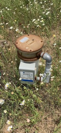
I’ve got a 1/2 HP (230v) submersible pump in my well and this has historically been used to supply a water trough for cattle so no pressure tank or switch. The set up has power running from a 30 amp breaker to a control box and that runs the well to fill the trough when the water level in the trough drops.
I’m in the process of completing a new barn and would like to run water to the barn (approx 150 feet from well) for a small bathroom (sink, toilet, etc.). My plan was to add a pressure switch and pressure tank to my current setup which seemed easy enough - take the power from the control box and route it to the pressure switch and then the wire pressure switch to control box (L1, L2 and ground). The well wire (R-Y-B-G) would stay as wired in the control box.
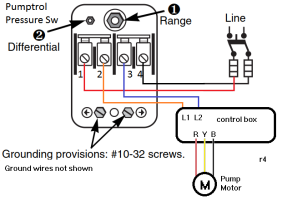
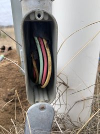
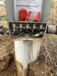
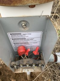
When I opened up the control box I saw two sets of wires coming from the well head and the hot wires from the breaker running to the well wires (connected with wire nuts) and then back out of the well to L1 and L2. There’s also some sort of 3 wire pigtail attached to L1 and L2 and grounded in the box too. Can somebody tell me what I’m looking at here and how I can go about adding my pressure switch and tank? I’ll try and attach the diagram of the current wiring.
My initial thought is move the R & G going to L1 and L2 and run them to the pressure switch and then wire the switch to the control box (L1 & L2) but I have no idea if that’s right. Any help would be greatly appreciated.
I’ve got a 1/2 HP (230v) submersible pump in my well and this has historically been used to supply a water trough for cattle so no pressure tank or switch. The set up has power running from a 30 amp breaker to a control box and that runs the well to fill the trough when the water level in the trough drops.
I’m in the process of completing a new barn and would like to run water to the barn (approx 150 feet from well) for a small bathroom (sink, toilet, etc.). My plan was to add a pressure switch and pressure tank to my current setup which seemed easy enough - take the power from the control box and route it to the pressure switch and then the wire pressure switch to control box (L1, L2 and ground). The well wire (R-Y-B-G) would stay as wired in the control box.
When I opened up the control box I saw two sets of wires coming from the well head and the hot wires from the breaker running to the well wires (connected with wire nuts) and then back out of the well to L1 and L2. There’s also some sort of 3 wire pigtail attached to L1 and L2 and grounded in the box too. Can somebody tell me what I’m looking at here and how I can go about adding my pressure switch and tank? I’ll try and attach the diagram of the current wiring.
My initial thought is move the R & G going to L1 and L2 and run them to the pressure switch and then wire the switch to the control box (L1 & L2) but I have no idea if that’s right. Any help would be greatly appreciated.