14/3 strange usage

Users who are viewing this thread

MrBillyd

New Member
Messages
10
Reaction score
0
Points
0
Location
Scottsdale
I am in the middle of demo and rebuild of 40 feet of softit removal and raising all of my ceiling up to 8ft.
The house was built in 79.
I have been re working the existing wiring so I can reinstall all the dry wall.
I found two strange usages of 14/3.
The home builder ran 14/3 for two different circuts instead of running 2 14/2.
So, instead of running 80 feet across the house with 2 14/2 he ran one 14/3 and shared the N.
In the living room the red hot wire goes thur a light switch to control a plug.
The black controls the other 4 outlets, garage lighting, door opener, utility rm lights, kitchen, hallway and entry way lights.
(Today I ran 2 new 14/2 feeds removing garage's 5 items, and another removing the utility and kitchen.)

Another situation they did this was in the kitchen, (same idea but with 12 awg wire) Red wire feeds the disposal, black the dishwasher and the counter outlets.
Does this type of shared N still happen today?

Also, I just bought a GFI outlet as my kitchen does not have one. Can you use a GFI with a circuit that has a shared N ?
Or will turing on the disposal trigger a GfI on the other circuit?

Thanks
Bill
 

ActionDave

Electrician
Messages
418
Reaction score
9
Points
18
Location
Colorado
.... instead of running 80 feet across the house with 2 14/2 he ran one 14/3 and shared the N....
Another situation they did this was in the kitchen, (same idea but with 12 awg wire) Red wire feeds the disposal, black the dishwasher and the counter outlets.
Does this type of shared N still happen today?
It is called a Multi-wire Branch Circuit. Yes they are legal, common, and still used today.

Also, I just bought a GFI outlet as my kitchen does not have one. Can you use a GFI with a circuit that has a shared N ?.....

Thanks
Bill
You can, but knowing how and where in the circuit to hook them up is a bit tricky. How brave are you?
 

Jimbo

Plumber
Messages
8,918
Reaction score
18
Points
0
Location
San Diego, CA
You have to be careful with the neutrals. I was once baffled for a while by a GFI trip...someone had tied some whites together in a box where a receptacle was fed from the GFI load side. That neutral from a different "hot" leg added an unbalanced flow back to the GFI and tripped it.
 

hj

Master Plumber
Messages
33,599
Reaction score
1,037
Points
113
Location
Cave Creek, Arizona
Website
www.terrylove.com
The shared neutral is ONLY legal when the two "hot" legs are on different sides of the incoming service. If they are on the same side, the amp loads on the neutral are added together instead of subtracted.
 

Hackney plumbing

Homeowner
Messages
1,130
Reaction score
3
Points
38
Location
Alabama
The shared neutral is ONLY legal when the two "hot" legs are on different sides of the incoming service. If they are on the same side, the amp loads on the neutral are added together instead of subtracted.

Explain this in detail HJ. Thanks for the post. I'm taking it as when you install the breakers for the two circuits(one 14/3 or 12/3 etc) one breaker should be on one side of the panel and the other breaker should be on the opposite side,corresponding to the two incoming feeds from the utility co.
 

JWelectric

Electrical Contractor/Instructor
Messages
2,608
Reaction score
21
Points
38
Location
North Carolina
Explain this in detail HJ. Thanks for the post. I'm taking it as when you install the breakers for the two circuits(one 14/3 or 12/3 etc) one breaker should be on one side of the panel and the other breaker should be on the opposite side,corresponding to the two incoming feeds from the utility co.

The breakers should be installed side by side so a handle tie will cause both breakers to turn off at the same time. This is a requirement of the new NEC.

If using a multi-wire circuit and you are a DIYer it would be a real good idea to use a two pole breaker for this circuit. This way you can’t go wrong.

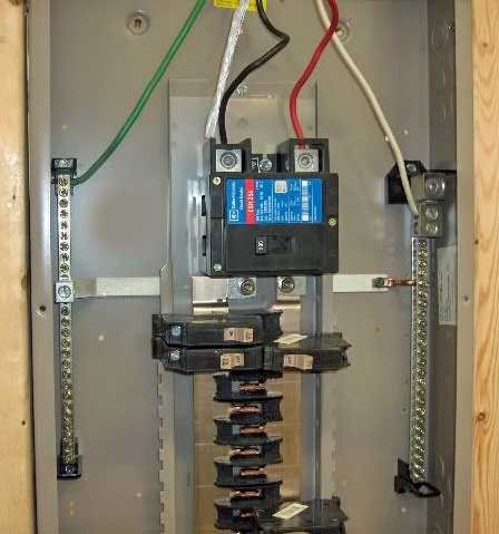
CHPanel.jpg


look at the bus bars of the CH panel. You can see that one breaker straight across form the other would be on the same leg but two breakers side by side would land on two legs of the panel.
When installing a multi-wire circuit it is important to be sure that the breakers land on opposing legs so the unblanced load is carried on the neutral. If both breakers are on the same leg the current adds on the neutral which will cause the insulation of the neutral to melt.
 

Hackney plumbing

Homeowner
Messages
1,130
Reaction score
3
Points
38
Location
Alabama
I see that when the breakers are aligned horizontally they would share the same leg of the supply but when installed "stacked" vertically directly above and below each other they are on seperate legs. The panel alternates. So let me get this straight about the principle of it.......since both circuits share the neutral and the neutral is the return path of a.c. current,the shared neutral would be the return path for both circuits and thats an overload aka "A house fire" LOL

What I really dont understand is why installing the breakers on different legs of the panel would prevent that.... I guess it's balanced that way? Thats the part I strugggle wit I think.

Thanks for your time. I dont plan on doing any wiring but its nice to learn. By the way,if this is such an issue why is it a new code? Seems like it would have been code long ago seeing it can burn houses down.
 
Last edited:

Jadnashua

Retired Defense Industry Engineer xxx
Messages
32,771
Reaction score
1,191
Points
113
Location
New England
You really don't have 120vac coming into the house, it's 240vac across the transformer with a 'neutral' connected half-way across the coil. If you connect between that half-way point and the either end, you get 120vac. One reason you may not get exactly the same voltage on one leg verses the other is that the neutral might not be perfectly centered. So, when one leg is going positive, the other leg is going negative, and half-way between them is a zero potential. If using vector math, the direction of the current vectors from each leg going back through neutral are exactly opposite - when added together, they equal zero.

If you do this and both feeds are on the same branch, both their current vectors are pointing exactly in the same direction, and with vector math, they add, so you now have double the current verses zero if done right. Since no one leg can exceed the max designed for that wire as protected by the CB, it can never exceed the wire's capacity, and if balanced, could be zero (probably doesn't happen too often).
 

Ballvalve

General Engineering Contractor
Messages
3,581
Reaction score
45
Points
48
Location
northfork, california
Seems like a no brainer that the bars alternate, other wise how could one obtain 240 volts on a double breaker?.... the lightest glance at a panel will show you that.
 

Hackney plumbing

Homeowner
Messages
1,130
Reaction score
3
Points
38
Location
Alabama
Seems like a no brainer that the bars alternate, other wise how could one obtain 240 volts on a double breaker?.... the lightest glance at a panel will show you that.

Yeah that makes sense but what doesn't make sense to me is why installing the breakers on separate legs of the 120 will keep the neutral from being overloaded. Its still only one neutral coming back to the main panel.
 

Nukeman

Nuclear Engineer
Messages
707
Reaction score
1
Points
18
Location
VA
The two legs are opposite in polarity, you could say. When #1 is going positive (towards +120v), the other (#2) is heading negative (towards -120v). The neutral remains in the middle. As #1 goes positive, the current for it will go one direction on the neutral, while the current to #2 will go the opposite direction on the neutral.

If the loads are exactly the same, the current on the neutral will cancel out (no net current). In the other extreme, you have the full load on 1 side and none on the other. In that case, the current on the neutral is equal to the current on that hot (the one with the load). So, if they are on opposite legs, you can't run into a situation where the neutral will carry more than either one of the hots.

Jim mentioned how it works, but maybe this will make it a little more clear.
 

Hackney plumbing

Homeowner
Messages
1,130
Reaction score
3
Points
38
Location
Alabama
Jim mentioned I really dont have 120 coming into the house but if I measure the voltage at an outlet thats what I get. How is that possible if I do not have 120 coming into the house?
 
Last edited:

Nukeman

Nuclear Engineer
Messages
707
Reaction score
1
Points
18
Location
VA
You have 240 V coming into the house with a neutral. The neutral splits the voltage in two. If you measured the voltage between the two hots feeding the house, you see 240v. If you measure between each hot and the neutral, you get 120v. Say your panel is all 120v circuits, half of the house is on one side of the incoming line and the other half of the house is on another.


Maybe it is easier to think about in terms of batteries. Say you have two 6v batteries. Connect the + of one to the negative of the other. If you now measure the voltage between the + of one battery and the - of the other, the voltage is 12v, right? This is how you can think about the supply to the house. Now if you measure between the + and - of either battery, each is still 6v (this is like your 120v circuits). So 240v = 2 batteries, 120v = 1 battery. Some 120v circuits are on battery #1, and the rest are on battery #2.

Now with the house voltage, the + and - flip back and forth. So, when circuits on battery #1 are + compared to neutral, the circuits on battery #2 are - compared to neutral.
 

Hackney plumbing

Homeowner
Messages
1,130
Reaction score
3
Points
38
Location
Alabama
You have 240 V coming into the house with a neutral. The neutral splits the voltage in two. If you measured the voltage between the two hots feeding the house, you see 240v. If you measure between each hot and the neutral, you get 120v. Say your panel is all 120v circuits, half of the house is on one side of the incoming line and the other half of the house is on another.


Maybe it is easier to think about in terms of batteries. Say you have two 6v batteries. Connect the + of one to the negative of the other. If you now measure the voltage between the + of one battery and the - of the other, the voltage is 12v, right? This is how you can think about the supply to the house. Now if you measure between the + and - of either battery, each is still 6v (this is like your 120v circuits). So 240v = 2 batteries, 120v = 1 battery. Some 120v circuits are on battery #1, and the rest are on battery #2.

Now with the house voltage, the + and - flip back and forth. So, when circuits on battery #1 are + compared to neutral, the circuits on battery #2 are - compared to neutral.

Oh ok.....My power meter and main panel box is outside. I have both 120 and 240 coming into the house depending on what appliance your checking at.

I found this info on multibranch.

.......................................................................................................................................................................
By David Herres

The following article was written when NEC 2005 was in force. NEC 2008 contains one significant Code change. Instead of only certain sensitive multiwire branch circuits, now all multiwire branch circuits must be protected by a double-pole breaker, not two single-pole breakers. In all cases, two single-pole breakers, linked by a listed device, are equivalent to a double-pole breaker.
Another important NEC 2008 change is that the ungrounded and grounded conductors of each multiwire branch circuit must be grouped by wire ties or similar means in at least one location within the panelboard or other point of origination. An exception provides that the requirement for grouping does not apply if the circuit enters from a cable or raceway unique to the circuit that makes the grouping obvious.

The very concept of a multiwire branch circuit, sharing a neutral between two circuits, appears designed to throw apprentice electricians into severe anxiety and disapproval.

It would seem obvious that two hot legs, both loaded close to maximum, would heat their shared neutral to such an extent that it would glow red hot as it passed through all that flammable material present in the walls of a wood frame building. Wouldn't it be best to call it "a multicircuit branch wire" and ban it forever?

Savvy electricians know otherwise and indeed the careful NEC allows a multiwire branch circuit if used properly. Actually such an arrangement, besides being Code compliant, has a few advantages and efficiencies which make it an attractive option. But there are some severe drawbacks as we shall see, and it may be that the outraged apprentices are right.

The whole idea is that the two hot wires have to be connected to different phases. Then, the neutral carries only the unbalanced current, the difference at any moment, between the more heavily loaded leg and its lighter colleague. In a single-phase circuit the neutral carries the most current when one leg is fully loaded (just under the amount that would trip the circuit breaker) and the other leg is not loaded at all. Then, as the amount of current flowing through the other leg increases, the neutral cools down. When both legs are equally loaded the two return flows in the neutral cancel and it is like the white wire is not there. In a run of conduit there is actually less heat than if the same two loads were on separate two-wire circuits. Besides saving wire, it is sometimes possible to use smaller conduit and on long runs voltage drop can be significantly lower. Additionally, 12-3 type NM is easier to install because it is round. There is definitely money to be saved.

Before considering the downside of these circuits that claim to eliminate a redundant neutral, let's see what NEC 2005 has to say.

The first mention is in Article 100-I Definitions. (Its presence there indicates that multiwire branch circuits are going to appear in more than one place in the Code. In fact, requirements are in eight locations.) "Branch Circuit, Multiwire. A branch circuit that consists of two or more ungrounded conductors that have a voltage between them, and a grounded conductor that has equal voltage between it and each ungrounded conductor of the circuit and that is connected to the neutral or grounded conductor of the system."

The main concept embodied in this definition is that the ungrounded conductors have to have voltage between them; that is they cannot be connected to the same leg. If they were connected to the same leg, the apprentice's worst fear would be realized - the shared neutral's ampacity would soar. Most electrical mistakes resulting in overloads will trip out the circuit breaker providing warning that something is wrong. But a misfed multiwire branch circuit will silently heat the neutral until it either burns clear inside an enclosure or ignites flammable building material resulting in property loss or worse.
 

BobL43

DIY Senior Member
Messages
1,802
Reaction score
8
Points
38
Location
Long Island, NY
Jim mentioned I really dont have 120 coming into the house but if I measure the voltage at an outlet thats what I get. How is that possible if I do not have 120 coming into the house?
because when you measure the voltage at that outlet, you are measuring from the Neutral to the hot leg at that outlet.
If that 2 pole breaker had a 1000 watt load on each pole of the breaker, the 2 loads would wind up being in series with each other fed by 240 volts, and the neutral would be handling little, if any current.
If one breaker had 1000 watt load on it, and the other pole of that breaker had a 250 watt load on it, then the neutral would be carrying the current for 750 watts at 120 volts 6.25 amps. If the 250 watt load was disconnected, then the Neutral would be carrying the full 1000 watt current at 120 volts 8.33 amps
 

Hackney plumbing

Homeowner
Messages
1,130
Reaction score
3
Points
38
Location
Alabama
because when you measure the voltage at that outlet, you are measuring from the Neutral to the hot leg at that outlet.
If that 2 pole breaker had a 1000 watt load on each pole of the breaker, the 2 loads would wind up being in series with each other fed by 240 volts, and the neutral would be handling little, if any current.
If one breaker had 1000 watt load on it, and the other pole of that breaker had a 250 watt load on it, then the neutral would be carrying the current for 750 watts at 120 volts 6.25 amps. If the 250 watt load was disconnected, then the Neutral would be carrying the full 1000 watt current at 120 volts 8.33 amps

Actually the water heater does not have a neutral. Just two 120v hots and a ground.
 

Nukeman

Nuclear Engineer
Messages
707
Reaction score
1
Points
18
Location
VA
That is because the WH is a 240v device. If it also needed 120v for something, it would also need a neutral to create a 120v source.
 

Nukeman

Nuclear Engineer
Messages
707
Reaction score
1
Points
18
Location
VA
Correct. The timer and such usually take 120v. This is true of many 240v circuits (such as a range). Pure 240v circuits (like a WH) only need the 2 hots and a ground.
 
Top
Hey, wait a minute.

This is awkward, but...

It looks like you're using an ad blocker. We get it, but (1) terrylove.com can't live without ads, and (2) ad blockers can cause issues with videos and comments. If you'd like to support the site, please allow ads.

If any particular ad is your REASON for blocking ads, please let us know. We might be able to do something about it. Thanks.
I've Disabled AdBlock    No Thanks