Jcwright30
New Member
Please do elaborate on this thought. Want to make sure I don't leave anything left out for a successful end product.Unless there was a possibility of cavitation. May not be possible at the flow rates anticipated.
Please do elaborate on this thought. Want to make sure I don't leave anything left out for a successful end product.Unless there was a possibility of cavitation. May not be possible at the flow rates anticipated.
Happy Monday All!If 28 psi is your static pressure (no flow) with no pump and no pressure tank, that means the water level in the cistern is 65' higher than where you are taking the measurement.
Your elevations must be off, as it's 65', not 90'. And a larger line won't change the static pressure; what it will do is reduce the frictional pressure loss that occurs during flow. Which is causing the the symptom "if you flush a toilet while a shower is running it's almost a trickle."
But, increasing the pipe size in the house won't do anything about the frictional pressure loss between the cistern and the house. Which is why Reach4 suggested taking 2 measurements at the yard hydrant--static pressure, and pressure while the shower is running. The difference tells you the frictional pressure loss between cistern and yard hydrant (and will increase with increasing flow, so with a helper or a video camera you could also take a pressure measurement at the yard hydrant when the toilet is flushed during a shower). Add to that the frictional pressure loss between yard hydrant and house, and that's all the pressure available to you at the house, without upsizing the outdoor piping.
Cheers, Wayne
Worthwhile test. This says that increasing the path size from the yard hydrant to the the kitchen would help a lot. Now to know if just changes in the house would be sufficient, you would need to put a pressure gauge close to where the water enters the basement.
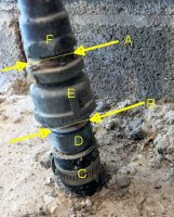
I suspect that the drop after the water has entered the basement may the bigger factor. What is the distance from the yard hydrant to the basement? What is the OD on that poly pipe in the basement?
")
OK - let's put the reconfiguration of the 3/4" pipe to 1" to the side for a bit. I installed the check valve last night and I'm a bit puzzled on the result...I don't understand all of what you propose, but I would not try to change out the barbed adapter. I don't know that you have 1 1/4" poly.
The reason the pump turned off is that the pressure switch told it to turn off.When i got the check valve installed and turned the pump back on it pumped for a very short time and only to about 35 PSI. The check valve is working as that pressure finally held. There is no water filling in the pressure tank. To ensure I didn't have a tank issue I drained and did as necessary to check the air pressure in tank (right around 38 PSI). I was hoping it was a minor blockage due to sediment but that wasn't the case. So now I'm left with the pump short cycling and the tank not filling up. Any ideas?

This makes sense in principle - what doesn't add up to me in my unique situation of having 28PSI of head pressure is why the tank doesn't fill up on its own (even with pump turned off). I'm expecting the tank would fill to hold 28PSI without the pump. But there is no water in the tank. The gauge reads 28 PSI because of the head pressure. If i shut off the supply water and open a faucet that 28 PSI almost pretty quickly falls to zero.The reason the pump turned off is that the pressure switch told it to turn off.
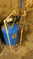
Much of the reason that the pressure switch turned off before the tank was filled to even its reduced capacity is that the pressure at the pressure switch was higher than the pressure at the pressure tank. You have a fairly long run of smallish pipe carrying water to the pressure tank. There is pressure drop during the flow of filling the pressure tank.
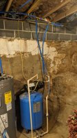
Ideally the pressure switch, or the far end of the sense line to the pressure switch, would be down by the tank tee. The sense line is that small tubing hooked to the pressure switch.
I was not trying to talk, you out of using bigger piping, but rather I was suggesting that you might consider larger stuff. A valve in the bypass line ideally should be a full port valve to add less restriction. I also thought it would be wise not try to replace the existing barbed ("insert") adapter at the poly pipe. You don't have room to cut that poly pipe back.
You have ~28 psi of air precharge in the pressure tank. At 28 psi, or less, of water pressure, no water enters the pressure tank. If the air precharge was 25 psi, just a little water would enter at 28 psi of water pressure.This makes sense in principle - what doesn't add up to me in my unique situation of having 28PSI of head pressure is why the tank doesn't fill up on its own (even with pump turned off). I'm expecting the tank would fill to hold 28PSI without the pump. But there is no water in the tank. The gauge reads 28 PSI because of the head pressure. If i shut off the supply water and open a faucet that 28 PSI almost pretty quickly falls to zero.
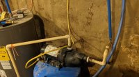
This tank/pump was with the house when i bought it but it was a package deal that was preassembled and installed by a reputable company. This is what has always eluded me also. So i should plug the sense line at the pump, relocate the pressure switch to the T fitting at the tank (there is room for it) and then run new wiring from pressure switch to pump.The line feeding the pressure switch can't be hook to the side of the pump its not looking at system pressure. When the pump runs it not looking at suction or discharge pressure but something else not full discharge. There should be a tap at expansion tank fitting.
Less informed or more lazy.Why would anyone have setup it up the way the did?
Have no idea unless your at the entering or discharge should being off the side of the impeller isn't a correct pressure reading.This tank/pump was with the house when i bought it but it was a package deal that was preassembled and installed by a reputable company. This is what has always eluded me also. So i should plug the sense line at the pump, relocate the pressure switch to the T fitting at the tank (there is room for it) and then run new wiring from pressure switch to pump.
Why would anyone have setup it up the way the did?
This is awkward, but...
It looks like you're using an ad blocker. We get it, but (1) terrylove.com can't live without ads, and (2) ad blockers can cause issues with videos and comments. If you'd like to support the site, please allow ads.
If any particular ad is your REASON for blocking ads, please let us know. We might be able to do something about it. Thanks.