Must Main Vent Stack attach vertically to Waste pipe?

Users who are viewing this thread

Elton Noway

Member
Messages
81
Reaction score
8
Points
8
Location
North Carolina
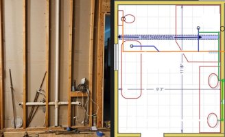
Just did a major gut job on our old 1980's master bath and closet area which included taking down three interior walls within that space. Of course... the last wall I took down exposed the main vent stack practically in the center of the room.

post.jpg

I will be constructing "one" new wall that will separate the closet area from the bathroom, Anyway... the plan is to move the vent stack 5 feet over and 2 feet back. In this way the stack will be located within the new wall I’m making and also pass up between the studs of a second floor closet and into the attic with no obstructions.

post1.jpg


My main concern is the outlet of the vent stack / drain connection i.e., plumbing “tree” will not be vertical at the point where it enters the drainpipe. I live in a state enforcing IPC code. I’ve read: . "the main stack should emerge from the top of the drainpipe, either straight vertically or at no less than a 45-degree angle from horizontal. … but want to make sure I'm interpreting this correctly.

All of the bathroom fixtures will be moved a little from their original location (vanity will move about 18”, toilet 36” shower drain 60”). As a result the “angles of the current connections points at the vent stack will no longer line up. To avoid any plumbing code exposures my plan is to “copy” the current plumbing drain / vent configuration design exactly, using all the same exact type connectors elbows, wye’s, 45’s, approach,. connection points etc. The one exception will be the how the main stack “assembly/tree” connects into main drain as it will not be dropping vertically into the drain but panning on making it a 45. (See photo below for an attempt at clarification) )

post 2.jpg

The Green box highlights the area (current plumbing) that I plan on copying, the (yellow lines) represent the new location of the vent stack and all drain connections. The current drain pipe to the septic runs parallel to the main support beam of the house (indicated by blue dotted line) . The new location for the vent stack entering the crawl space will be within 30" of the drain pipe but will be on the opposite side of the support beam. Will I be okay if I copy the previous plumb job as mentioned above but have the stack exit with a 45 entering the drain pipe?
 

James Henry

In the Trades
Messages
1,579
Reaction score
404
Points
83
Location
Billings, Montana.
"the main stack should emerge from the top of the drainpipe, either straight vertically or at no less than a 45-degree angle from horizontal. …
 

wwhitney

In the Trades
Messages
6,567
Reaction score
1,847
Points
113
Location
Berkeley, CA
In this way the stack will be located within the new wall I’m making and also pass up between the studs of a second floor closet and into the attic with no obstructions.
So this stack doesn't drain anything from the second floor, yes?
To avoid any plumbing code exposures my plan is to “copy” the current plumbing drain / vent configuration design exactly, using all the same exact type connectors elbows, wye’s, 45’s, approach,. connection points etc.
This is probably not the best choice. From your picture the existing drain configuration looks fine (except how is the vanity vented?), but there are many ways to plumb a bathroom. Since you are moving fixtures and moving the stack, you have the opportunity to start fresh, and a different drain configuration may be simpler or better for your new arrangement. And the existing drain configuration may not work in the new location, if some of your fixtures are too far away from that new location.

So I suggest you post a dimensioned floor plan of the new arrangement, showing the walls where your vent can rise up, showing the location of all the fixtures, and showing the main girder below (which you outlined in dashed blue).

This it is relatively simple to mark up that floor plan with suggestions on the drain routing and how to vent everything.

Cheers, Wayne
 

Elton Noway

Member
Messages
81
Reaction score
8
Points
8
Location
North Carolina
So this stack doesn't drain anything from the second floor, yes?

This is probably not the best choice. From your picture the existing drain configuration looks fine (except how is the vanity vented?), but there are many ways to plumb a bathroom. Since you are moving fixtures and moving the stack, you have the opportunity to start fresh, and a different drain configuration may be simpler or better for your new arrangement. And the existing drain configuration may not work in the new location, if some of your fixtures are too far away from that new location.

So I suggest you post a dimensioned floor plan of the new arrangement, showing the walls where your vent can rise up, showing the location of all the fixtures, and showing the main girder below (which you outlined in dashed blue).

This it is relatively simple to mark up that floor plan with suggestions on the drain routing and how to vent everything.

Cheers, Wayne
Hey Wayne, Thanks for the detailed response!
Sorry for the delay.. been a while since I used the only drafting tool I have on my pc. (had to re-learn it. As to your first question.. you are correct the main stack doesn't drain anything from the second floor, it's strictly a dry vent. As to how the vanity was vented, I figured a picture would be better than me trying to explain it. The image below has 3 sections - the left and center image are shots of the bathroom from opposite angles, the far right image is in the attic. NET: The vent for the vanity (is indicated by the light blue dotted lines)- From the vanity drain, it runs up the vanity wall across the bathroom above the ceiling, then through the ceiling into the attic where it ties into the main stack. An interesting layout but it seems to work. For the new vanity I was planning on going vertical off the drain inside the new partition wall then making a short horizontal run over and tie into the stack in its new location (also in the new wall. NOTE The wall partition wall hasn't been built yet so its not in the photos but the is accurately represented in the drawing you requested.

vanity vent.jpg


As to my drawing below, each square in the drawing represents 1 square foot. The drawing is pretty close to scale but adding the fixtures was pretty much a free hand exercise hopefully they're close enough. The small black circles in each fixture represent the new drain locations. The tub is one of those little 28"x59" slipper tubs (a must have per the wife) The new vent stack location is in the wall on the right as is the vanity drain. (I included the old location just for reference). The not so good news is the new location for the vent stack now falls on the other side of the house main support beam, the good news is I'm able to standup in the crawl space having almost 6 feet of clearance to work in. Let me know if this works. If I misunderstood what you were looking for or left anything out please let me know.

NEW LAYOUT_ .jpg
 

wwhitney

In the Trades
Messages
6,567
Reaction score
1,847
Points
113
Location
Berkeley, CA
OK, here's my first thoughts on how to plumb the DWV on that. Orange = 3", Blue = 2", Green = 1-1/2". IPC applies in NC.

First, I'm keeping the two lav drains separate. They have the only dry vents, and those dry vents need to rise vertically to at least 6" above the lav flood rims before turning horizontal. Above that elevation, they can go horizontal through the wall to get to your desired vent location, or that could happen in the attic. Each lav only needs a 1-1/2" vent, and they could combine to a 1-1/2" vent (again at least 6" above the fixture flood rim) or a 2" vent if you like. And the vent should expand to 3" before exiting the building thermal envelope if you are in a cold climate (expand on the vertical with a funnel-shaped reducing coupling so that any water (rain) coming down the vent will have no place to get trapped). There is no need to have a full 3" vent from the 3" drain through the roof (under the IPC).

Second, the horizontal drains I've drawn are below the bottom of the floor joists, except the segments I drew that cross the girder or are above (on the page) the girder, which are within the joist bays. So for example, the WC drain starts off between the floor joists (hopefully the closet flange isn't over a joist), then where it turns to run left-right on the page, it drops down below the joists (e.g. quarter bend to turn to 45 from plumb, then a 45 to turn horizontal again). Same for where the shower drain joins the 3" line. Also, I drew the upper (on the page) lav drain as crossing over the girder to indicate it at the higher elevation (passing over the 3" line below the joists), but it could meet the shower drain farther down the page if desired.

The basic idea in the two elevations of horizontal pipes is that the tub and shower traps need to be vented before they fall one pipe diameter (2" in both cases as drawn, although you can use a 1-1/2" trap and trap arm for the tub if you prefer). And the shower is on the far side of the girder, so its trap arm wants to be above the girder to cross it; while the tub trap arm wants to be below the floor joists to travel under them (minimize drilling). So I kept the two lav drains separate, using one to wet vent the shower (higher elevation trap) and the other to wet vent the tub and WC.

Note that the tub drain needs to join the WC/lav downstream of where the lav joins the WC, as drawn. That is why the lower (on the page) lav drain proceeds to the left (on the page) so far before turning up (on the page) to join the WC drain and wet vent it.

The only joists you should have to drill for this plan are the left-right (on the page) portions of the upper (on the page) lav drain. You could in theory drop the shower trap so that its drain is below the girder, and avoid drilling any joists (and allowing the lav drains to be combined), but the tailpiece is IIRC limited to 24" vertically, which looks like it wouldn't work. Plus it would be low and in the way. I would suggest keeping the new work mostly as high up as possible to preserve head room, dropping down just where you tie into the existing. The maximum elevation of the 3" WC going under the joists would be determined by the elevation of the 1-1/2" lav drain coming over to wet vent it, and the 1/4" drop per foot necessary on that lav drain.

Note that this plan has nothing resembling the existing "octopus". The existing configuration was primarily a vertical wet vent; this configuration is all horizontal wet venting.

Cheers, Wayne


NEW LAYOUT_ .jpg
 

Elton Noway

Member
Messages
81
Reaction score
8
Points
8
Location
North Carolina
Wow... I never expected this kind of response but I for one really appreciate the time, trouble, thought and detail that went into your response. Thank you for all the detail and subsequent explanations. I've read through it all twice... but... not being in the trade I'll need some time to digest the information so I'm sure more questions will follow. My biggest take away was your suggestion to convert to horizontal wet venting (eliminating the octopus) Awesome! Not being in the trade I never considered (probably because I didn't know it was an option) . Sounds easier that what I was envisioning.

To make sure I understand, in regards the lav vents... you mentioned "they "could" combine to a 1-1/2" vent". Below is how they were originally configured (as shown in this photo). Would doing it the same way still be okay versus running separate drain lines or does a separate drain allow for better operation and venting at the 3" line? For clarity purposes only, I moved one of the green lines in your drawing to combine the two lavs. If separate drains vent operation is not a good idea let me know... just curious
combined vent.jpg

Next question: In a couple instances you mention running drains lines or traps "between the floor joists". In keeping with your design (and referring to your drawing) I'm assuming you mean parallel to them but just below the bottom edge of the joists rather than physically in between them. Between duct work, insulation, water lines, electrical etc... doing anything between the joist gets a little crowded.

FYI: Currently all the drain lines regardless of their orientation are suspended 1 to 2" below the bottom edge of the floor joist. The main sewer line is down 24" from bottom of the joist so I have plenty of room to install the traps below the bottom edge of the floor joist while still having room to make drops down to the sewer.

Still trying to get my head around the "elevations". Thanks to your drawing and explanations I understand which fixtures are to be downstream from another but our drawings represent an overhead view looking down. I'm now trying to envision a view looking at the layout it from the side and imagining how the pipes should angle down (on both sides of the support beam) to join the main sewer pipe (guessing no less than 45 degrees. At this point I'm not sure if any one drain connection to the sewer line (tub, shower, or lav) has to be vertically higher or lower in relation to each other.

Last... it appears I'll be running a 3" line from the WC over to the wall where the dry stack enters the equation, picking up the tub and shower drains connections along the way however I'm not exactly sure where / how I introduce and connect the the main vent stack.

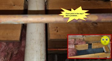
SIDE NOTE: Funny you should mention "hopefully the closet flange isn't over a joist" ... not sure is this was acceptable back in 1980 but a floor joist didn't stop the plumber from installing the toilet flange (Discovered this during the demolition).

cut_joist.jpg
 
Last edited:

wwhitney

In the Trades
Messages
6,567
Reaction score
1,847
Points
113
Location
Berkeley, CA
To make sure I understand, in regards the lav vents... you mentioned "they "could" combine to a 1-1/2" vent". Below is how they were originally configured (as shown in this photo). Would doing it the same way still be okay versus running separately drain lines or does a separate drain allow for better operation and venting of the 3" line?
To clarify, my layout does not show the vents, it only shows the drains. The green circles are where the lav drains enter the floor after being dry vented, and the simplest way to dry vent them is to have a san-tee directly above those locations, with the lav trap arm entering the wall into the side entry of the san-tee. Then the top of each san-tee is a 1-1/2" dry vent. That dry vent has to rise further in the wall, at least to 6" above the fixture flood rim, then above that elevation the dry vents can turn horizontal in the wall and/or combine (if desired).

So with respect to what my drawing was showing, what you have done is move the lav drains, not the lav dry vents. And now the WC and the tub are not vented at all (they had been wet vented by the lower on the page lav drain), so it doesn't work.

Next question: In a couple instances you mention running drains lines or traps "between the floor joists". In keeping with your design (and referring to your drawing) I'm assuming you mean parallel to them but just below the bottom edge of the joists rather than physically in between them. Between duct work, insulation, water lines, electrical etc... doing anything between the joist gets a little crowded.
No, I meant physically in between the joists, on the assumption that the joist bays in question are or can be made free of obstacles. The issue is that the WC and the shower are on the opposite side of the girder from everything else, and so how are those drains going to get to the other side of the girder? They obviously can't go through the girder.

The WC could actually drop down below the girder and then be wet vented as normal, as the WC fixture drain has no limit on fall before being vented (this is an exception compared to most fixtures). The shower trap arm, however, must be vented before it falls more than one pipe diameter in elevation. And the shower tailpiece is limited to 24" in length (actually it's from the shower drain in the floor of the shower to the trap weir, the point water spills out of the trap u-bend into the trap arm). So if you lower the shower trap so the trap arm is below the girder, does that fit within the 24" allowed? Even if it does barely, I figured that going above the girder was a nicer solution that going under the girder.

So let me know about that. To the extent your drawing's grid is to scale, I drew about 3' of 3" WC drain in one joist bay (before it drops as it turns to run perpendicular to the joists but under them), 3' of 2" shower drain in another joist bay, 5' of 1-1/2" lav drain in a third joist bay (although that doesn't really have to cross the girder, it could be only 4' long), and a 1-1/2" lav drain going through 1-2 joists as it runs 2'+ through the joists.

Last... it appears I'll be running a 3" line from the WC over to the wall where the dry stack enters the equation, picking up the tub and shower drains connections along the way however I'm not exactly sure where / how I introduce and connect the the main vent stack.
As I mentioned, you don't need a 3" main vent stack, the (2) 1-1/2" lav dry vents suffice. And so there is no 3" main vent stack in my drawing, and the 3" horizontal drain never connects to a 3" vertical dry vent.

I mean you can add such a dry vent stack connection if you want, but it seems awkward with the desired stack location on the opposite side of the girder from the existing horizontal 3" branch heading off the right of the page. Since this unnecessary 3" dry vent would have to rise vertically all the way to above the flood rim levels of the fixtures. So the simplest way to do that would be change the routing of the 3" WC drain quite a bit.

Cheers, Wayne
 

wwhitney

In the Trades
Messages
6,567
Reaction score
1,847
Points
113
Location
Berkeley, CA
P.S. I guess if you prefer to have all the drains below the joists, that can be done if you dry vent the shower by running its trap arm under the location where you had intended to have a 3" vent stack anyway. That way the unvented shower trap arm can be below the joists but above the bottom of the girder, and it can get dry vented at that elevation, then it can drop down to pass under the girder. Plus then you could combine the two lav drains at the vanity area, since you no longer need a separate lav drain to wet the shower.

Or if you are OK with just the 5' run of 1-1/2" lav drain between the joists, then you could still use that to wet vent the shower trap arm at this elevation alongside the girder, and you wouldn't have to drill any joists.

Let me know if you prefer either of those, and I can draw it up that. In which case please repost the floor plan in post #4 with all of the stuff I deleted pre-deleted for me.

Cheers, Wayne
 

Jeff H Young

In the Trades
Messages
8,954
Reaction score
2,235
Points
113
Location
92346
semi unusual situation regarding walls there are no walls inside the bathroom at tub or shower in case a vent might be looking for a wall to rise up , presumeably a 3 ft space for toilet followed by an 8 ft space for a tub no wall between not that you have to have one but maybe there is and it might be a good place for a vent for toilet and or tub same with shower . Im not making suggestion right now just thought it might help you get the details figured on the vents
 

Elton Noway

Member
Messages
81
Reaction score
8
Points
8
Location
North Carolina
So with respect to what my drawing was showing, what you have done is move the lav drains, not the lav dry vents. And now the WC and the tub are not vented at all (they had been wet vented by the lower on the page lav drain), so it doesn't work.
Ah... my mistake... I understand now, makes sense, Thanks. Will stick with your original design

No, I meant physically in between the joists, on the assumption that the joist bays in question are or can be made free of obstacles. The issue is that the WC and the shower are on the opposite side of the girder from everything else, and so how are those drains going to get to the other side of the girder? They obviously can't go through the girder.
.
So if you lower the shower trap so the trap arm is below the girder, does that fit within the 24" allowed? Even if it does barely, I figured that going above the girder was a nicer solution that going under the girder.
Ah... I'm beginning to see a disconnect. Sorry... it appears I failed to mention the top edge of the support beam is "flush: with the top edge of the floor joists. With subfloor installed there's zero space above the beam (see photo) so my only choice is to drop and go under it. Because I knew there was no space above the beam I incorrectly assumed "allL the drain lines in your drawing passed under the main beam

mainbeam.jpg


As I mentioned, you don't need a 3" main vent stack, the (2) 1-1/2" lav dry vents suffice. And so there is no 3" main vent stack in my drawing, and the 3" horizontal drain never connects to a 3" vertical dry vent.

I mean you can add such a dry vent stack connection if you want, but it seems awkward with the desired stack location on the opposite side of the girder from the existing horizontal 3" branch heading off the right of the page. Since this unnecessary 3" dry vent would have to rise vertically all the way to above the flood rim levels of the fixtures. So the simplest way to do that would be change the routing of the 3" WC drain quite a bit.

More confusion on my part. In my original drawing I indicated the new location of the 3" dry stack because I thought a vent was necessary so the sewer could pull in air at some point. Guess its apparent I don't have a grasp on how wet venting works. So... if I don't use the 3: vent I assume I'd have to go up on the roof and cap it off?

Just an idea... not sure if there would be any benefit... but the current main 4" sewer line that is located below the bathroom being remodeled, runs 35 feet (before dropping and turning out to the septic). As long as I maintained the proper 1/4 bubble slope (and if allowed) I could cut the line (at the area indicated by the red circle), and put in a couple 45's so a new section of sewer pipe would be on the other side the beam. But... other that being able to have the dry vent stack drop vertically into the sewer pipe I'm not sure if makes any difference because main beam would still separate the WC and shower from the tub and lav drains
sewerline_cut.jpg
.
 

wwhitney

In the Trades
Messages
6,567
Reaction score
1,847
Points
113
Location
Berkeley, CA
Ah... I'm beginning to see a disconnect. Sorry... it appears I failed to mention the top edge of the support beam is "flush: with the top edge of the floor joists.
Ah, I had a photo interpretation mistake. I thought photo #3 in the OP showed a dropped girder, but looking again it is a flush beam, which is also clear from photo #1. So all of my comments so far have been for the case of a dropped girder, with just blocking between the joists over the girder.

The flush beam definitely makes things easier, and I can give you a new simplified layout based on this. But I will await the requested emptier version of your floor plan for me to mark up.

Also, looking at your last photo, I see that there are some large ducts occupying the elevation that is 0" to 24" below the floor joists. Could you show those on your floor plan? As well as the pier locations? I assume it would be easier to pass the drains under all the ducts, but if necessary looks like you could drop a duct 6" or so to pass a drain over one of the ducts.

More confusion on my part. In my original drawing I indicated the new location of the 3" dry stack because I thought a vent was necessary so the sewer could pull in air at some point. Guess its apparent I don't have a grasp on how wet venting works. So... if I don't use the 3: vent I assume I'd have to go up on the roof and cap it off?
A dry vent extends from a trap arm through the roof. A wet vent is a drain from a dry-vented fixture that functions as a vent, connecting a different fixture's trap arm to that dry vent.

Both your lavs will be need to be dry-vented, so those vent(s) will need to connect to your existing roof penetration. It's just that you don't need a 3" dry vent that goes all the way from the 3" / 4" drain below the floor up through the roof.

Cheers, Wayne
 

Jeff H Young

In the Trades
Messages
8,954
Reaction score
2,235
Points
113
Location
92346
Gobs of room Im not seeing a problem I was wondering about the girder comment wayne made looks like its an open hiway
 

Elton Noway

Member
Messages
81
Reaction score
8
Points
8
Location
North Carolina
P.S. I guess if you prefer to have all the drains below the joists, that can be done if you dry vent the shower by running its trap arm under the location where you had intended to have a 3" vent stack anyway. That way the unvented shower trap arm can be below the joists but above the bottom of the girder, and it can get dry vented at that elevation, then it can drop down to pass under the girder. Plus then you could combine the two lav drains at the vanity area, since you no longer need a separate lav drain to wet the shower.

Or if you are OK with just the 5' run of 1-1/2" lav drain between the joists, then you could still use that to wet vent the shower trap arm at this elevation alongside the girder, and you wouldn't have to drill any joists.

Let me know if you prefer either of those, and I can draw it up that. In which case please repost the floor plan in post #4 with all of the stuff I deleted pre-deleted for me.

Cheers, Wayne
Darn... sounded like the solution until I read "the unvented shower trap arm can be below the joists but above the bottom of the girder". As mentioned in my reply above the bottom of the girder is also the bottom of the joists, with no space above the girder / support beam.

Sorry for all the trouble. Here's a repost of my original drawing... but you might want to hold off until you've determined I haven't forgotten any other details. FYI... my plan includes two knee / partition walls (one between the toilet and tub and one between the shower and the vanity... but I didn't include them since they aren't floor to ceiling. The only wall for venting is the one where I indicate the new vent stack location.

Looking at this diagram a simple rectangle... the top edge of the drawing is a load bearing wall with necessary framing support above and below that prevents any significant penetration. The bottom edge wall is also a load bearing wall with the same restrictions. The left hand wall is the brick exterior with support beams sitting on a sill plate. The right hand wall is free floating. I built it after tearing out the orignal wall which was 18" to the right. I moved it over to enlarge the master closet on the other side. I hated taking space away from the bathroom but the closet, which was 11' deep... was only 36" wide. It had one long closet rod and very little room to move when clothes were hanging.

NEW LAYOUT.jpg
 

Jeff H Young

In the Trades
Messages
8,954
Reaction score
2,235
Points
113
Location
92346
why not offset the main back a ways and come up in the "new vent location" and pick up shower and w/c from there ? and perhaps using a wye where doing that offset picking up the lavs and tub off a 2 inch branch or bushing down a 3 inch wye to continue to lavs and tub. Sorry I know Im not real clear . Id kinda like to use that 3 inch vent if its easy.
Wayne probebly brainstorming up something good LOL !
 

Elton Noway

Member
Messages
81
Reaction score
8
Points
8
Location
North Carolina
semi unusual situation regarding walls there are no walls inside the bathroom at tub or shower in case a vent might be looking for a wall to rise up , presumeably a 3 ft space for toilet followed by an 8 ft space for a tub no wall between not that you have to have one but maybe there is and it might be a good place for a vent for toilet and or tub same with shower . Im not making suggestion right now just thought it might help you get the details figured on the vents
If needed... guess I could install a floor to ceiling wall on the left side of the shower (i.e. the section of the shower between its left edge and the toilet. I was originally planning a small partial / knee wall about 34" deep in that hat location but I could take it all the way to the ceiling if that helps with the plumbing. Unfortunately, due to the limited space, the toilet will be in the minimum allowable space 30" wide space (i.e. wall to knee wall) We have another bathroom with a toilet in a 30" space and it works fine for us. Once the toilet knee wall is in there will only be 7 feet of workable space left when allowing for swing of the entry 30" entry door.
No secret these older homes weren't necessarily known for their opulent bathrooms or massive walk in closets. :(
FYI: The wife wants to but a 59" inch slipper / soaker tub under the window. :rolleyes:
 

Elton Noway

Member
Messages
81
Reaction score
8
Points
8
Location
North Carolina
Please add the knee walls (maybe dotted), the ducts (if they are under the bathroom footprint), and the pier locations.

Cheers, Wayne
Here you go... No hard ducting in between joists... its all 8" flexible ducting tubes. I pulled it down during demo. I plan on putting a floor vent in down the road. Let me know if you need anything else. THANKS
NEW LAYOUT_2 .jpg
 
Last edited:

Jeff H Young

In the Trades
Messages
8,954
Reaction score
2,235
Points
113
Location
92346
What I was getting at is the vent for toilet can be right where your new vent was proposed , vent for shower as well
 

wwhitney

In the Trades
Messages
6,567
Reaction score
1,847
Points
113
Location
Berkeley, CA
OK, below is a simpler layout, now that I understand the floor framing system. Orange = 3" drain under the floor; Blue = 2" drain under the floor ; Green = 1.5" lav trap arm above the floor; Dashed Green = 1.5" dry vent at an elevation at least 6" above lav flood rim (could be in the wall; could be between ceiling joists).

The lavs get a common drain and vent; the vent runs from the lav location over to the desired location for the vent stack to pass through the floor above. The drain for 2 lavs now has to be 2" to be used as a wet vent. This lav drain / wet vent runs over to the tub vicinity to pick up the tub drain and wet vent it. Then the tub/lavs joins the WC drain and wet vents it. Lastly the shower drain joins in and is wet vented (IPC does not require the WC to be last on the wet vent).

Comments: the tricky part is venting the tub. For a dry vent, you indicated the top and left walls (on the page) are out. So the only option would be if you add that potential partition wall and use it to dry vent the tub. Which would be a fine option (easy for me to draw out) if you desire to have a solid wall there, but I wouldn't say it's a reason to use a partition wall there instead of glass if you prefer glass.

Then if you aren't going to dry vent the tub, you have to went vent the tub, and the only option I see is to use the lav drains as is typical. That makes the lav drain take a circuitous route out of the area, but that's fine.

As to elevations, all the 2" and 3" drain lines under the floor are pitched 1/4" per foot, with no other drops or changes in elevation (except where you tie into the existing, not shown). If you want everything as high as possible, then the limiting factor is where the lav drain first enters the floor system and turns horizontal. If that's just under the floor joists, then as its path winds it way around to pick up the tub, WC, and shower, and then exits the bathroom foot print, it runs 16'+, so it drop 4"+ while doing so.

Cheers, Wayne


NEW LAYOUT_2 .jpg
 
Top
Hey, wait a minute.

This is awkward, but...

It looks like you're using an ad blocker. We get it, but (1) terrylove.com can't live without ads, and (2) ad blockers can cause issues with videos and comments. If you'd like to support the site, please allow ads.

If any particular ad is your REASON for blocking ads, please let us know. We might be able to do something about it. Thanks.
I've Disabled AdBlock    No Thanks