iwen
New Member
A supply of 110v was supplied to a 220v contactor, after sometime the contactor got burnt, why? does it mean a 220v contactor could not withstand 110v power? please help.
Lee, check the OP's location.However, I would doubt the coil was expecting 240 volts in the first place since control voltages are usually only 120 VAC or 24 VDC (even when the circuit being controlled has a higher voltage).
... in a motor starter or in a commercial/industrial setting a contactor coil may very well be 240v, and typically is.
If you have a straight 240v single or three phase load why bring a neutral in just to power the coil?
In my last project, I did not want to run 480 through the control pendant.
Why?
LeeAnything I say here is likely going to be spun into something to try to make me look incompetent, ignorant or even stupid, but oh well ...
First, because the only thing I actually know how to do with *3-phase* power is that of wiring and connecting contactors and motors. But beyond that, I needed control voltage and pendant wiring for a 110-volt double-acting hydraulic valve (for leveling the beam hanging on the hook) as well as for the reversing starter for the turn motor for the drums and straps ... and along with that, I needed a 12-volt circuit in the pendant for starting the hydraulic pump in conjunction with the aforementioned valve ... and I already had 120VAC available since it was needed for charging the hydraulic pump's and air compressor's battery. But of course, maybe 480 for all of that would have been much easier for a real electrician, eh?!
Lee
I am not sure that I fully understand what you are saying here. No I am not trying to make you look incompetent in any way just trying to understand what you are saying.
This is what I understand you to have said ...
It would help if you would take the time to explain just what you are lifting and what is being done with the product that is being lifted.


Lee, check the OP's location.
9 out of 10 times this is a burnt coil not any real problem with the actual contacts or mechanism. Low voltage to the coil for a while will burn em up.
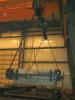
If I understand this correctly we have an overhead crane that is powered by 480 volts.
This crane has two 12 volt direct current electric motors that operate an air compressor and a hydraulic pump.

Well I am going to leave this one alone ...
... but will ask why these tanks that are designed to be buried underground must be handled so delicately? Are they not reinforced by some sort of rebar?
This is awkward, but...
It looks like you're using an ad blocker. We get it, but (1) terrylove.com can't live without ads, and (2) ad blockers can cause issues with videos and comments. If you'd like to support the site, please allow ads.
If any particular ad is your REASON for blocking ads, please let us know. We might be able to do something about it. Thanks.