Want to add speed control to a single speed circulator pump

Users who are viewing this thread

jeffsnavien240ncb

New Member
Messages
16
Reaction score
0
Points
1
Location
Maryland
I have a 1/10 hp pump with the ball valves closed considerably; I am not sure if this is ok for the pump.
I think maybe if I can retro in a speed controller might be another solution.
Has anyone done this?
can I use a ceiling fan light dimmer speed controller?
Could I use a blower motor speed controller rheostat ?
http://www.grizzly.com/products/Router-Speed-Control-20-Amp/G3555

http://www.ebay.com/itm/Variable-Fa...ex-Blower-Exhaust-Control-1800W-/191063176059

http://www.homedepot.com/p/Lutron-S...ntrol-White-SFSQ-FH-WH/100399013?N=5yc1vZc32s
 

DonL

Jack of all trades Master of one
Messages
5,205
Reaction score
72
Points
48
Location
Houston, TX
If it is working you should leave it alone.

You can put a lightbulb in series with it, just for play. Tells you when it is running too.


Good Luck on your project.
 

Dana

In the trades
Messages
7,889
Reaction score
509
Points
113
Location
01609
Increasing the flow increases the heat throughput to the radation, increasing the average water temp of the system. Throttling it back would normally make the house colder, and would make the problem WORSE, not better. The solution is elsewhere.

AC pump motors are not designed for speed control- they are single speed devices. Using dimmer waveforms on them is not a good idea.

What are you using for a boiler? If for some reason the higher flow is problematic for the boiler or it's controls, there is probably going to be more appropriate way to deal with it than cranking down the flow to the radiation.
 

jeffsnavien240ncb

New Member
Messages
16
Reaction score
0
Points
1
Location
Maryland
the house was cold I did some reading an seemed that the water was moving to fast I adjusted the ball valve and the house got warm.

What do you mean: (what am I using the boiler for, like steaming fish is an option? heating a house duh!) yeah I am making fish taco's for all, come on over; yikes?
SO if the solution is elsewhere, please say something then.
 

Dana

In the trades
Messages
7,889
Reaction score
509
Points
113
Location
01609
That's "What are you using for a boiler?", not "What are you using the boiler for." (It could be awkward to parse if English isn't your first language I suppose.) It's pretty common to use water heaters of various configurations as space heating boilers, and depending on make/model and how it's configured affects the plumbing and control configurations.

I can't speculate with any insight unless you fill in the blanks on how much and what type radiation you have on each zone, what the boiler is, how it's plumbed and pumped, etc.

All radiation puts out more BTU/hour at higher gallons per minute than at low gpm. Pumping faster lowers the delta-T across the radiation, which may affect the boiler's internal controls (or not) depending on the boiler and how it's plumbed/pumped. Hot return water pipes <==> hot radiation <==> higher BTU/hour. Try actually measuring the temperature of the pipes the initial input to the radiation as well as that of the return water pipes- the measured delta-T is a useful parameter for the analysis.

If slowing down the pumping on the radiation is causing the boiler to put out more heat, it's likely that something in the system topology is a bit askew, and some plumbing fixes may be in order. If you can sketch out the piping system showing all pumps (including any that may be internal to the boiler) and zone valves etc. and radiation (amount & type per zone) it could be a starting point for that discussion.
 

Dana

In the trades
Messages
7,889
Reaction score
509
Points
113
Location
01609
Maybe a stretch, but based on his forum name, I'm going to guess he is using a Navien NCB-240.
http://us.navien.com/Product/Page1/Details/NCB-240?Category=NCB series

There are still other blanks to fill in.

I was figuring that too, but didn't want to bark up that tree unless he made it explicit, since I'm not getting a clear picture out of statements like. " ...I did some reading an seemed that the water was moving to fast I adjusted the ball valve and the house got warm."

I'm supposing that the reading he was doing wasn't necessarily the Bhagavad Gita or Torah, and that the house getting warm wasn't about the sun rising, but who knows? :) Some clues as to where to find the relevant chapter & verse of scripture that led to thinking high flow was part of the problem would be useful too.
 

LLigetfa

DIYer, not in the trades
Messages
7,502
Reaction score
577
Points
113
Location
NW Ontario, Canada
I'm not getting a clear picture out of statements like. " ...I did some reading an seemed that the water was moving to fast I adjusted the ball valve and the house got warm."
The problem of finding information on the internet, assuming that was where the OP read that, is that it is sometimes an exercise in apophenia.
 

jeffsnavien240ncb

New Member
Messages
16
Reaction score
0
Points
1
Location
Maryland
P1100485.JPG


how's that for a sketch


(sorry lots of long and late days of work) I miss read your Q, but your still welcome to come over for fish taco's
 
Last edited:

Dana

In the trades
Messages
7,889
Reaction score
509
Points
113
Location
01609
As a schematic it's pretty lousy since it doesn't tell flow directions, and some of the fittings are obscured. But it's way better than a 10,000 word description.

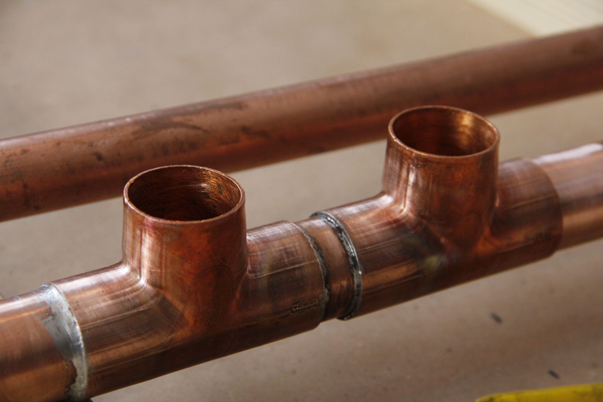
There appears to be at least one plumbing error of significance on the hydraulic separation plumbing. The tees where the primary loop branches into/out-of the system loop (the tees closest to the boiler) need to be very closely spaced. They should not more than 4 pipe diameters (looks like you have at least 6-7 pipe diameters between the tees), and closer is even better. Even with fatter diameter pipe they should not more than 12", per the instructions on p.28 of the manual. Commercial hydraulic separators are typically many times the diameter of the plumbing going into them, with the loops plumbed to flow across each end of the hydraulic separator to minimize the interaction between the primary & secondary pump flows, effectively isolating them from a pump-pressurization point of viewlimiting the amount of primary loop flow that gets induced by the secondary pump:

HydroCal.gif
Hysep_Page_3_Image_0003.jpg


That's also the ideal location for the expansion tank too, which makes it something of a shock-absorber.

If you can make the room, move the expansion tank to the other side of the tees too, so both the primary loop pump (the one inside the boiler) as well as the secondary pump (the green Taco) is pumping away from the expansion tank. Where it is currently located the secondary pump is pumping away from the expansion tank (which is correct), but the primary pump is pumping toward the expansion tank with the impedance of the heat exchanger and primary loop plumbing between the pump and the expansion tank.

On the return side of the primary loop tees there is also a U-turn made of ells (?), very close to the tees, which introduces some undesirable turbulence just before the point where it hits the point of hydraulic separation (the stub of pipe between the tees).

With that much pipe between the tees and the induced turbulence on the secondary just prior to the separator, the secondary pump flows are interacting with the primary loop flows, which may be causing the boiler to kick off at higher secondary flows(?). Piping per the installation manual would be an important first step. Make sure you have at least 8" of straight pipe on the secondary loop on both sides of the tees, and butt the tees as close as possible, to minimize the interaction at the point of hydraulic separation.

The contractor who installed it SHOULD make those changes at no charge, since at least the max spacing of the tees is spelled out in the installation manual. But even if you have to pay somebody, that's a good start, and has a good chance of making the thing behave properly over a wide range of radiation flow rates.

A schematic of what you have, including the approximate lengths of the radiation runs, etc. may still be useful.
 

jeffsnavien240ncb

New Member
Messages
16
Reaction score
0
Points
1
Location
Maryland
thanks for your in depth look and reply; the measured distance between the T's is 8.5" that should be ok isn't? It is less than the 12 inches' specified. (
P1100506.JPG
maybe this photo is better)
 

Jac04

Member
Messages
139
Reaction score
3
Points
18
Location
Connecticut
Per the instructions, it's " Not to exceed 4 pipe dia. or a max. 12" ". You can't just use the max. 12" as the limit if 4 pipe diameters is less than 12".
 

Dana

In the trades
Messages
7,889
Reaction score
509
Points
113
Location
01609
What jac04 said. If 12" is more than 4 pipe diameters, it's too long. Even the 4 pipe diameters is a maximum, not an optimal. If that's 3/4" pipe you're looking at 11 pipe diameters, which isn't even CLOSE to being in spec for primary/secondary piping with tees, which is what I was pointing out.

Not in the manual, but still a real issue, you can't just stub out of the tee and make a quick U-turn like that, the way the return line is tied in. Even the 90 degree ells on the primary loop that close to the tee isn't great. Ideally you's have at least a foot of straight pipe on all connections to the hydraulic separation point.

If you don't have room to do it right using closely spaced tees, making up a hydraulic separator with a six inch stub of 2" pipe and a pair of 2" x 3/4" reducing tee (or a 2" tee with reducers to the 3/4" right at the tees) would do even better than closely spaced tees.

If doing it with tees, this is what it should look like:

012013-080.jpg


But make sure all stubs coming into the tees are at least 8" long straight pipe, not a collection of twisty turny ells.

A lot of hydronic pressure-magic has to happen in the 2-3" between the tees for this to work, and there are several ways to screw it up. As-plumbed yours exhibits most (but not quite all) the ways to screw it up. (At least the flow direction is correct, eh? :) )
 

jespinosa

New Member
Messages
1
Reaction score
0
Points
1
Location
Seattle, WA
So, how do you control speed on a recirculating pump? Voltage control (ie. variac), or pulse-width-modulation or current limiting. Is this even possible? Isn't it a simple ac motor? I have Grundfos pumps, some 3 speed others 1 speed.
 
Top
Hey, wait a minute.

This is awkward, but...

It looks like you're using an ad blocker. We get it, but (1) terrylove.com can't live without ads, and (2) ad blockers can cause issues with videos and comments. If you'd like to support the site, please allow ads.

If any particular ad is your REASON for blocking ads, please let us know. We might be able to do something about it. Thanks.
I've Disabled AdBlock    No Thanks