Trouble with new tub and old (formerly) drum trap drain

Users who are viewing this thread

Chassis

Engineer
Messages
340
Reaction score
0
Points
16
Location
SE Pennsylvania
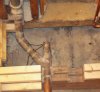
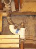
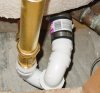
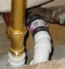
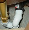
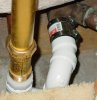
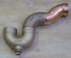
Good day folks. Putting in a new tub. Old one was connected to a drum trap. I've fiddled with plastic p-trap pieces and for the life of me can't figure out how to make it work, with the space provided. The drain line is pretty close to the centerline of the tub tailpiece. I'm pretty sure it is less than what is needed for a p-trap, in order to connect standard sweep 45's and 90's. It is pretty close to the minimum distance for a drum trap.

Question - are drum traps illegal across the board, or is it a local municipality issue? If I use a brass drum trap, I think I can make it work. The old one is ancient history, I cut it out with a sawzall during demo.
 

Chassis

Engineer
Messages
340
Reaction score
0
Points
16
Location
SE Pennsylvania
Another thought for the same issue - what is the proper use of a sanitary tee or long sweep tee? I am thinking of running the vertical vent into the "radius" part of the sanitary tee, with the tub drain entering upstream of the radius. This is essentially what I have now, but instead of a sanitary tee, there is a brass wye. Problem I have is the location of the wye is creating issues in getting the tub drain connected without relocating the vent or wet drain pipe (after the wye) in a major way.

I want to put the sanitary tee horizontally, with the sweep arm vertical, or nearly so. The vent would enter the sweep arm from above, and would be directionally correct. The drain would flow through the "straight" (my words) part of the tee.
 
Last edited:

Chassis

Engineer
Messages
340
Reaction score
0
Points
16
Location
SE Pennsylvania
Is this arrangement code compliant? I think it will get me where I want to go. It is a copper p-trap and two street 45s. The tub tailpiece feeds into the p-trap, then the last 45 is connected to a short nipple, then enters the existing DWV wye, where the vent stack joins the drain. This is all 1 1/2" piping. Thanks.
 

Attachments

  • trap.jpg
    trap.jpg
    49.5 KB · Views: 2,737

Cass

Plumber
Messages
5,947
Reaction score
7
Points
0
Location
Ohio
If you can shorten the piece coming down from the tub, raise up the trap, and eliminate the 45s then it will work. Do you have a vent there somewhere?

You don't want to install it the way you are showing it.

Why arent you using a banded coupling from copper to PVC pipe to PVC trap and up to the waste and overflow with a desanco / trap adaptor?
 
Last edited:

Chassis

Engineer
Messages
340
Reaction score
0
Points
16
Location
SE Pennsylvania
Cass,

Thanks. I can't raise the trap higher because it's as high as the tailpiece will allow. There is a vent after the trap. Why don't I want to install it as shown, is it a convenience issue or against something in plumbing code? Just trying to understand the situation.

Another problem I have is there is not much pipe length from the trap to the wye. I want to leave the wye where it is, because moving it means modifying the vent line, which will be a pretty major headache.
 

Cass

Plumber
Messages
5,947
Reaction score
7
Points
0
Location
Ohio
What will happen if you cut the tail piece shorter?
 

Chassis

Engineer
Messages
340
Reaction score
0
Points
16
Location
SE Pennsylvania
Here are some more pics. The first pic shows the copper wye and vent pipe. The tub trap (not shown) goes in the notch in the joist. The wye, as you can see, is just below the top of the joist.

Second pic shows what I think will work. From the vent line, use a banded coupling to connect the PVC 90 deg. elbow. Then a short length of PVC into the sanitary tee. Upstream of the sanitary tee would be PVC, eventually reaching the tub tailpiece. Downstream of the sanitary tee would be another banded coupling, which connects into the existing copper drain line.

The two basic questions here are 1. Is this code?, and 2. Will this work? Thanks again for all the assistance. :)

p.s. I promise not to use blue tape to glue the fittings together. ;)

p.p.s. Why don't the images appear automatically? For me they only show up as links.
 

Attachments

  • vent.jpg
    vent.jpg
    69.6 KB · Views: 1,297
  • vent2.JPG
    vent2.JPG
    85.7 KB · Views: 1,264

Chassis

Engineer
Messages
340
Reaction score
0
Points
16
Location
SE Pennsylvania
Is this kosher? Here is the setup:

1. Kohler pop up drain assembly tailpiece
2. 1 1/2" PVC p-trap
3. 22.5 degree 1/16 street bend
4. short 1 1/2" nipple (not visible) on hub end of 1/16 bend, inside of Fernco
5. 1 1/2" Fernco coupling
6. cast copper wye (existing)

The trap arm and existing drain line are about 4 1/4" offset, which is why I needed the 1/16 bend.

You can see the vent line coming in from the right.
attachment.php

p.s. I still can't see these photos in the thread, they are shown as links which are only viewable when you click on them. Is there a solution to this?
 

Attachments

  • trap_070209.JPG
    trap_070209.JPG
    77.9 KB · Views: 4,191
  • trap_070209_2.jpg
    trap_070209_2.jpg
    83.9 KB · Views: 1,802
Last edited:

hj

Master Plumber
Messages
33,603
Reaction score
1,042
Points
113
Location
Cave Creek, Arizona
Website
www.terrylove.com
drain

1. That Fernco is not approved for that location.
2. You need a proper "transition" coupling with one side sized for PVC and the other for copper.
3. I would not use a "union joint" trap in a location like that. The nut joining the two parts can crack and cause a leak.
4. That short radius trap will cause problems if the drain becomes obstructed and has to be snaked some day.
 

Chassis

Engineer
Messages
340
Reaction score
0
Points
16
Location
SE Pennsylvania
hj,

Thanks for the feedback. How does this look? Here is the setup with some changes:

- Coupling is now American Valve No Hub Coupling 1 1/2", part no. RNH40. I took out the Fernco Plumb Quick P1056-150. The Fernco label indicates it is for use with copper, steel, lead and plastic.
- Trap is now a solvent weld; no union nut, except at the tailpiece.
- Still have the 1/16th street bend and short nipple into the No Hub.

I don't understand the point about a "short radius trap". All the PVC 1 1/2" traps I looked at at HD and Lowe's had the same radius on both the bottom u-turn and the outlet ell.

Thanks.
 

Attachments

  • trap_070209_3.jpg
    trap_070209_3.jpg
    76.1 KB · Views: 1,335
  • trap_070209_4.JPG
    trap_070209_4.JPG
    75.2 KB · Views: 1,210
Last edited:

hj

Master Plumber
Messages
33,603
Reaction score
1,042
Points
113
Location
Cave Creek, Arizona
Website
www.terrylove.com
drain

The problem with the Fernco was not the size, it was its material and design. If it were being used outdoors AND underground it would have been okay. Indoors, whether above ground or below, it cannot be used. If that is truly a "NoHub" coupling then it is also improper because it is made for cast iron on both sides. You need a transition sized for PVC on one side and copper on the other. That is a short radius trap because it has the union joint and is intended for use under a kitchen sink, not under a tub. You should be using the one with a glued joint between the two pieces.
 

Chassis

Engineer
Messages
340
Reaction score
0
Points
16
Location
SE Pennsylvania
Thanks for the feedback guys. hj, do you have a recommended manufacturer for a transition coupling? HD and Lowe's don't carry anything besides the improper Fernco in the earlier picture. I have a couple good plumbing supply houses nearby, but want to know what I am asking for.

The flexible coupling I used is American Valve RNH-40. It's made from neoprene if that matters.
 
Top
Hey, wait a minute.

This is awkward, but...

It looks like you're using an ad blocker. We get it, but (1) terrylove.com can't live without ads, and (2) ad blockers can cause issues with videos and comments. If you'd like to support the site, please allow ads.

If any particular ad is your REASON for blocking ads, please let us know. We might be able to do something about it. Thanks.
I've Disabled AdBlock    No Thanks