In most cases the right thing to do would be to isolate the Takagi's pumping rate from the radiation pumping rate with separate pumps, a "primary-secondary". Done that way you can run the Takagi at a fairly high delta-T with high efficiency without pumping the hell out of it, which takes a toll on flow sensors and even erodes internal plumbing. Even if they're capable of 4-6 gpm in peak water heating mode, it doesn't mean they tolerate that at a high duty cycle. But they CAN tolerate very high delta-Ts of 70-80F at 2 gpm at a high duty cycle.
But the open system heat/hot water system complicates that, since you can't just crank up the temp of the Takagi to get the high delta-T.
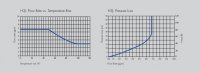
Try running some fuel-use math to come up with a reasonable estimate of the design heat load. A 2gpm flow is about 1000lbs/hr, a 4 gpm flow is about 2000lbs/hr. So if the design heat load comes out to say, 40,000 BTU/hr at your 99% outside design temp, at 2000lbs/hr (gpm) that's only a 40K/2K= 20F delta-T needed out of the tankless. At 1000lbs/hr (2 gpm) it would need a 40F delta-T out of the tankless.
If the radiant floor design only need 90F water on design day (pretty common with radiant slabs), with the tankless cranked up to 130F you'd be able to get there with a 2 gpm pump on the primary side (the tankless loop) and you can run whatever monster flow you think you need through the heating system. But that puts you in scald territory on the hot water. At 3gpm (1500lbs/hr) that's a delta-T of 40K/1.5K= 27F, so you can set the tankless to a more reasonable 117F out.
The pumping on the heating system side probably doesn't need to be more than 1gpm, but you can play with it independently.
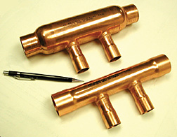
To make a cheap hydraulic separator between the two sides, take some 1" or 1.25" copper tees and solder them to as short a stub as possible, so that there are fewer than 4 pipe diameters center to center. Use reducers or reducing tees to 3/4" for the primary side, and make sure the secondary side and primary side flows are in the same direction through the fat stub of pipe, not counter-flow. There may be some flow tweaking to do here so a ball valve on the primary loop to be able to raise/lower the flows & delta-Ts isn't a bad idea. But with a hydraulic separator in place the radiation flows can vary by quite a bit without affecting the primary flow through the tankless by very much.
In this diagram they've reversed the primary & secondary sides, which reflects the needs of a high boiler flow requirement and low radiation flow, but with a tankless as the "boiler" the low-flow side is the primary.
Here's a picture of a pre-manufactured version- fatter is generally better for flow separation on the stub:
") ) With no new water, there are no new mineral deposits.
) With no new water, there are no new mineral deposits.