Switched Wiring

Users who are viewing this thread

DavidDeBord

Member
Messages
42
Reaction score
2
Points
8
Location
Hamersville, Ohio
Greetings Wayne,

It's according to the AHJ, which I'm sure that You are familiar with.

Here, via the Clermont County Building Dept., that is also capable of Commercial Inspections,... Wants that fridge on a separate circuit.

And, in order to obtain that "Blue Card", & get paid,.... I have to comply.
 

DavidDeBord

Member
Messages
42
Reaction score
2
Points
8
Location
Hamersville, Ohio
I've wired many a residential home, & where the HO would have a large diner/party, with every outlet being used,... Sure enough, Issues would come up, over having enough Power.

I Installed four separate 2o Amp GFI circuits at the counter top for My Wife, fully knowing that she'd be including all kinds of Appliances while cooking, & that is what I recommend for My Customers.
 

WorthFlorida

Clinical Trail 5th session completed 4/24/24.
Messages
5,763
Solutions
1
Reaction score
998
Points
113
Location
Orlando, Florida
NEC Requirements: (Having more circuits is never a problem)
Provide at least two 20-amp, 120-volt circuits to supply power to GFCI (Ground Fault Circuit Interrupter) receptacles for countertop and eating areas.
A receptacle outlet must be installed for every kitchen and dining area counter wall space 12 inches or wider. Receptacles must be installed so that no point along the counter wall space is more than 24 inches (2 feet), measured horizontally, from a receptacle outlet. (48 inches between outlets.)
 

Thomas K

Member
Messages
353
Reaction score
16
Points
18
Location
Opelika, al
Wow! Since I was slammed at work today (master auto tech) I missed out on the discussion until this evening. So I will clarify situation:

1. I did recheck wiring to refrigerator outlet, and it is on a dedicated 20 amp circuit with 12 gauge wire.

2. Kitchen countertop is L-shaped, with one outlet on small part of L and two more outlets on other section, one on each side of kitchen sink. All are on same circuit, and I'm hoping wiring is 12 gauge, although I need to check.

3. Problem is wiring layout. House is a split-level, but is built like a two story house with a section over to one side. Bottom floor is concrete (some of it looks like brick flooring) with concrete block walls. These block walls support second floor as well as dividing den and two smaller rooms. Some of the wiring for first floor runs along the top of these block walls (and I'm not sure that's a good thing) and a lot of it runs up from breaker box through second floor bedroom wall to attic. I checked crawl space underneath kitchen and I don't see any wiring going up to kitchen. From what I can see, outlet wiring goes over ceiling joists in attic and down through kitchen walls near eaves, making access difficult.
 

Attachments

  • IMG_1920.JPG
    IMG_1920.JPG
    78.3 KB · Views: 174

WorthFlorida

Clinical Trail 5th session completed 4/24/24.
Messages
5,763
Solutions
1
Reaction score
998
Points
113
Location
Orlando, Florida
The black cables laying across the rafters is not original to the house. I'm sure in '63 that would have to been tied down. This post has gotten pretty wide in discussion and may have drifted from your original post. You do not have to add anything to the kitchen if you are not remodeling it.
  • Are you just want to update some circuits and add one for the freezer?
  • Please take a picture of the breaker panel and what is the amperage of the main, 60a, 100a or 150a.
  • Do you think it is original or has it been upgraded?
 

Thomas K

Member
Messages
353
Reaction score
16
Points
18
Location
Opelika, al
Outlet for freezer is in same room as breaker box. so I can just run a 12 ga. wire over to it. Walls are open because I wanted to see if wiring was ok. Someone wired up a few lights in the two small rooms adjoining den, and they had two outlets wired into these light circuits. So I ran new light wiring and disconnected outlets. One outlet I will tie back in with those lights, and one I will run 12 ga. wire for dedicated freezer outlet to breaker box.

Of course, someone framed up concrete blocks with no insulation and wood touching block, so I will have to insulate and reframe.

The breaker box has been upgraded; it's a 125 amp main breaker Square D Homeline box, Square D sticker had this number: 40265-668-03, and there was also a Homeline sticker with the number BXH26-24-A. There are 24 breaker slots in it, or 48 with thin breakers.

Someone installed it upside down because of the way the service wiring comes in, but failed to secure box to cement block. It's just sitting there. And wife and I had home inspected before we bought it.
 

Attachments

  • IMG_1901.JPG
    IMG_1901.JPG
    103 KB · Views: 193

Thomas K

Member
Messages
353
Reaction score
16
Points
18
Location
Opelika, al
Image 1939 is a telephone company ground. I'm really wanting to replace that pipe with Pex and reroute it. Is there any way I can wire a jumper from that telephone ground over to bonding wire? Or run a green insulated ground jumper back to breaker box? Since all of that is being replaced with Pex, I will likely have to run a new bonding wire over to cold water pipe coming up through first floor concrete anyhow, as I'm pretty sure it's necessary.
 

Attachments

  • IMG_1939.JPG
    IMG_1939.JPG
    63.6 KB · Views: 200
  • IMG_1940.JPG
    IMG_1940.JPG
    81.9 KB · Views: 197
Last edited:

wwhitney

In the Trades
Messages
6,567
Reaction score
1,847
Points
113
Location
Berkeley, CA
So what is your grounding electrode system? Assuming you don't have a concrete encase electrode, it should most likely be a bond to the metallic water service within 5' of entering the building, plus 2 ground rods.

Then per NEC 250.94 you are supposed to install an Intersystem Bonding Terminal. They are basically busbars for the grounding connections for the telephone, cable, etc., and they come in versions that attach either to the service panel or to one of the grounding electrode conductors/jumpers. Then you move your telephone ground to the IBT.

Cheers, Wayne
 

Thomas K

Member
Messages
353
Reaction score
16
Points
18
Location
Opelika, al
I'm, not sure exactly where grounding electrode is, Wayne, and didn't know what an IBT was until you mentioned it . Telephone ground is connected to copper pipe, and bonding 8 ga. ground wire is attached to same copper pipe. There's about 4' between them. 8 ga. bonding wire runs over to ground bus in breaker box. Worked on house today, and most of the old copper is gone now. I did leave the section where the grounds are connected intact.
 

wwhitney

In the Trades
Messages
6,567
Reaction score
1,847
Points
113
Location
Berkeley, CA
Rather than write a long post that covers all the possibilities, let me ask how big your ungrounded (hot) service conductors are (can be hard to tell, don't touch them, if you're lucky you can read the writing) and how large your service disconnect (main breaker in the service panel) is.

Assuming #2 Cu or smaller and 125A or smaller, then #8 is the correct minimum size for your grounding electrode conductors (GEC). Then you want to end up with these 3 grounding electrodes: the first 5' of copper pipe water pipe within the house (you can switch to PEX after the GEC connection), and 2 ground rods, at least 8' long, fully buried, and at least 6' apart. Each grounding electrode gets a #8 Cu connection to the ground bar in your main service panel. At least one of those connections must be a single unspliced piece of copper from the ground bar to the ground clamp on the electrode. The other connections can have splices, and can connect to the ground bar, or to another GEC. Likewise, I suggest connecting the telephone ground to one of the #8 Cu GEC, using a split bolt or equivalent.

To find grounds rods, you can trace the #8 Cu on the water pipe to the ground bar, and then look for similar conductors leaving the ground bar, also similar conductors connected to the water pipe GEC.

Cheers, Wayne

P.S. You may want to double check that #8 Cu size. A #8 GEC is supposed to be run in conduit; #6 is allowed to be bare if it follows the surface of the building and is not exposed to damage. So if it's really #8, it's probably simplest to replace with #6, and just use #6 everywhere.
 
Last edited:

Thomas K

Member
Messages
353
Reaction score
16
Points
18
Location
Opelika, al
I'm probably wrong about the grounding wire being 8 gauge; it is a large wire with no insulation so it's probably 6 ga, unspliced from breaker box to clamp on copper pipe.

Another note: copper bonding (grounding?) wire is stapled to underside of 2nd floor joists.

I'm not sure of the wire gauge of service wires coming in, but main breaker is 125 amp. Wire that is connected to water piping from telephone company looks to be maybe 14 gauge. It runs about 3' over to the concrete block wall of first floor and goes somewhere. And it's definitely not connected within the first 5' of water pipe coming in now. Water pipe comes up from concrete in other room about 10-12' away.

Wayne, I think you're telling me breaker box and main service wiring needs to be attached to two ground rods, with an unspliced bonding wire going from grounding bar in breaker box to copper pipe near main water valve. And that I need to install a bonding terminal (like in photo?) and attach bonding wire jumper from water pipe and telephone wire to it. Would bonding terminal mount on joist?

I'm not sure how many grounding rods are sunk for the main service, but I'm betting it's only one. I'll have to look outside around where service comes in. If I need another, I will hire an electrician.

I'm leaving copper piping coming into the house and copper pipes from it to kitchen sink. The rest will be replaced with Pex, including the piece with the grounds on it.
 

Attachments

  • bond.jpg
    bond.jpg
    25.1 KB · Views: 165
Last edited:

wwhitney

In the Trades
Messages
6,567
Reaction score
1,847
Points
113
Location
Berkeley, CA
OK, let me try again.

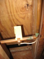
You should have 3 electrodes: (1) if your water service is metal (copper) and underground for at least 10', then you should connect to it either outside, or inside within 5' of it entering the building. (2 and 3) two grounds rods, at least 6' apart, each one in contact with the earth at least 8', so fully buried if only 8' long (which is convenient, you can bury the connection and the conductor going to it).

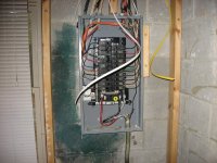
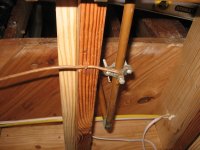
Pick one electrode. Run an unspliced #6 copper conductor from the service panel neutral/ground bar to the electrode and connect it with a proper grounding clamp for the electrode type (water pipe or ground rod). For the other electrodes, you again use a grounding clamp for a #6 copper conductor, but this jumper conductor can have splices, and you can run it to any where convenient: an electrode already connected to the panel, or to one of other #6 copper conductors you've already run, or back to the main panel. You could even do it all with a single unspliced conductor, if you want, going from the panel to one electrode to the next in a daisy chain.

Now use a properly sized split bolt to connect the telephone grounding wire to any of the #6 copper grounding conductors, wherever is convenient.

That's the state of affairs you want to get to. If you find you have only one ground rod, and it is currently connected with an unspliced #6 conductor to the service panel (so it meets the unspliced requirement), then you can just extend the conductor going to the water pipe to the proper location within 5' of entering the building. And you can drive a second ground rod 6' away or more, and run a jumper conductor to the existing round rod, or the #6 conductor going to it.

Cheers, Wayne
 

Thomas K

Member
Messages
353
Reaction score
16
Points
18
Location
Opelika, al
Okay. I was thinking the copper wire going from pipe to breaker panel was to ground the pipe in case a power wire shorted on it somewhere. Evidently, the copper wire is used to ground the breaker panel through the copper pipe system going underground. And to bond the copper piping to the electrical box. I read in another article that there is supposed to be another wire attached near the water meter, as well.

I am assuming that my electrical breaker box is grounded by separate ground wires going to sunken ground rods, but is it possible that the wire going to copper pipe is the only ground? If so, I have ungrounded the breaker box by cutting the piping nd after the ground wires.

I'll see what grounding rods are present tomorrow.
 

Thomas K

Member
Messages
353
Reaction score
16
Points
18
Location
Opelika, al
Looked for grounding rods today and found none, unless they are completely buried somewhere. But there is no other ground wire connected to neutral bus in breaker box except for the main service uninsulated neutral wire coming in. Service wires go into concrete block wall inside a steel tube. Meter is on other side of this wall, but a little higher up, so I'm assuming the service wiring goes through concrete block up to it. There is a cable box as well as a telephone box on exterior wall near meter, and both have ground wires tying onto ring at top of meter where the wires come in from a street power pole. I saw no uninsulated conductors coming down from power meter to ground. Meter itself is one of the newer digital ones.

tried to check for wire gauge by looking at insulation on incoming service wires, but it is just wiring with red and black plastic wrapping and no markings. I tried to trace the interior telephone wire and it looks like it goes around top of interior block wall and exits out to telephone box. Warning tag on ground wire said South Central Bell, which has been defunct since 1992. I think company is owned by AT&T now. Maybe I should have an electrician come out and look at it.
 

wwhitney

In the Trades
Messages
6,567
Reaction score
1,847
Points
113
Location
Berkeley, CA
Sounds your telephone has two grounds, which would be redundant.

You definitely want to drive two ground rods for the electrical service.

Cheers, Wayne
 

Thomas K

Member
Messages
353
Reaction score
16
Points
18
Location
Opelika, al
I know a guy who owns an electrical repair company in Auburn, AL. They do good work. I'll ask him tomorrow how much it would cost to send one of his guys out to install new ground rods and check that telephone ground.
 

Thomas K

Member
Messages
353
Reaction score
16
Points
18
Location
Opelika, al
Electrician came out today. He did a good job, but only installed one ground rod. I had to get back to work, but it was my understanding that two rods would be installed from the electrician's boss. Electrician told me that when he was finished I would not need a ground on copper pipe as it was old school. He told me not to worry about the telephone ground, or disconnect it, as telephone company would re-ground to new ground wire when internet service installed. I will call back to confirm order in the morning. There was a copper gas line coming out of ground in this area so maybe there was a problem there.

Regardless, I am having them install two ground rods, as that is what I wanted in the first place. I think I need to run a ground wire from panel over to the copper water pipe, as well.
 
Last edited:

Aaroninnh

Member
Messages
146
Reaction score
20
Points
18
Location
NH
Code does not require 2 ground rods. Only required when resistance to earth is more than 25 ohms. Many electricians just do two so they dont have to perform a ground resistance test and/or have the tool on-hand to do it.

Also, since rods are being driven and the GEC changed, should ensure the electrician installs the required intersystem bonding termination device. Its basically a ground bar that gets installed external from the panel (often next to power meter) and is for the use of the telco, satellite TV guys, and everyone else who tends to do low rent grounding jobs by trying to put corner clamps on your power meter.


They usually have a lay-in lug spot so it can clamp right to your GEC.

https://www.supplyhouse.com/Arlingt...MIgt6Eod-K7gIVh4NaBR1jAQjREAQYASABEgI7d_D_BwE
 

wwhitney

In the Trades
Messages
6,567
Reaction score
1,847
Points
113
Location
Berkeley, CA
Code does not require 2 ground rods. Only required when resistance to earth is more than 25 ohms. Many electricians just do two so they dont have to perform a ground resistance test and/or have the tool on-hand to do it.
It does not literally require 2 ground rods, as you say, but it effectively does. Because (a) 25 ohms to ground is very hard to achieve with a single rod in most all soil types and (b) driving a 2nd rod is cheaper/easier than doing the ground resistance measurement, which is likely to be insufficient anyway.

Also, since rods are being driven and the GEC changed, should ensure the electrician installs the required intersystem bonding termination device. Its basically a ground bar that gets installed external from the panel (often next to power meter) and is for the use of the telco, satellite TV guys, and everyone else who tends to do low rent grounding jobs by trying to put corner clamps on your power meter.
That's a fine choice, but is not required in existing buildings, to my knowledge. So if the telephone and cable are properly grounded now, leaving it alone is a good option. If they aren't properly grounded now, using an intersystem device would be a good way to go.

Cheers, Wayne
 
Top
Hey, wait a minute.

This is awkward, but...

It looks like you're using an ad blocker. We get it, but (1) terrylove.com can't live without ads, and (2) ad blockers can cause issues with videos and comments. If you'd like to support the site, please allow ads.

If any particular ad is your REASON for blocking ads, please let us know. We might be able to do something about it. Thanks.
I've Disabled AdBlock    No Thanks