Stumped by no heat to new heater

Users who are viewing this thread

WGus

New Member
Messages
4
Reaction score
0
Points
1
Location
Naperville, IL
My brain teaser is this: a 60 year old boiler heats 4 one-bedroom apartments and does a fine if inefficient job. However one bathroom has always been cold, so I added two 1/2 inch copper lines, supply line is about 15', to feed a new hydronic kickspace heater. All existing lines from manifolds are 3/4 galvanized. The manifold tees I used were already there and look exactly like all the other tees, no indication that they're monoflo. Problem: at the end of the 15' supply line the copper is stone cold! I bled all air out thoroughly so definitely know water is in the lines. How can the water be so cooled off in such a short, well-insulated run? Two theories:
1) I have a 5" nipple (3/4) from the supply manifold connected to a reducing elbow, valve, then copper. Is that size reduction impeding flow from the 2" manifold when all other radiators have 3/4" galvanized?
2) Could I have oversoldered one or more of the sweat joints reducing my pipe capacity? I researched (Youtube) after doing the work and think I may be overly zealous with solder.

Input is appreciated!
 

Dana

In the trades
Messages
7,889
Reaction score
509
Points
113
Location
01609
You don't have low flow, you have NO flow! Even a half-inch line that's half-blocked with solder (unlikely) would have sufficient flow to make the distribution lines hot.

If both the supply and returns to the toe-kick heater are teed-in to a loop anywhere near each other one or the other or both have to be mono-flow tees to make it work.

Can you post some pictures?
 

WGus

New Member
Messages
4
Reaction score
0
Points
1
Location
Naperville, IL
Thanks Dana. Pic of my branch off supply (the one with valve) and existing branch, both tees identical (second pic). Two new pieces of info:
1) Getting better educated on manifolds, I think I can state mine are parallel not loop, terminating at both ends - hence no need for mono-flow? Also, these tees are about in the middle, not the end
2) I've noticed a very significant difference in pipe temp before and after the reducing tee. I'm wondering if that means I should have installed 3/4" for the 15' and reduced before the 1' vertical connection to heater rather than reducing after 6" nipple?
 

Attachments

  • 20180116_105409[1].jpg
    20180116_105409[1].jpg
    56.3 KB · Views: 336
  • 20180116_105522[1].jpg
    20180116_105522[1].jpg
    51 KB · Views: 387

Dana

In the trades
Messages
7,889
Reaction score
509
Points
113
Location
01609
The pumping head of the coil in a toe-kick heater is many times that of a few feet of 1" plumbing or even 25' of half inch. You're not going to be able to fix this by swapping plumbing diameters.

Either pull the nipple between the tees and plug them, forcing the full system flow through the toe-kick heater (which could be problematic), or install a ball valve in place of that nipple to be able to raise the pumping head of that section of pipe (tweakable with the valve) just enough to get adequate flow through the toe kick coil. Odds are you don't need or want the full system flow to go through the coil, so closing it only partially to where the heater functions OK without reducing the flow on the whole system too much is less risky than turning it fully off.

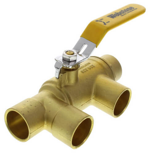
One of these (called a "loop purge tee") will probably do the trick, and likely easier to retrofit than one built up with fittings (which would of necessity take more length, length that may not be available.)


58644-4.jpg


Fill_wPurgeTee.png


Other than that you'd be looking at buying a pump to force flow through the toe-kick heater coil.
 

WGus

New Member
Messages
4
Reaction score
0
Points
1
Location
Naperville, IL
I appreciate your feedback, but maybe I've not been clear about my set-up. The nipples in the pic are coming from the 2" supply manifold (I added the one with the valve), and directly to the right is the 2" return manifold. They don't connect anywhere. Not pictured is the nipple and .5 copper line I added that connects the heater return line to the return manifold.
 

Dana

In the trades
Messages
7,889
Reaction score
509
Points
113
Location
01609
Can you make a careful sketch? A picture is worth 1000 words, and so far it's well under that 1000 words...

In your first picture you have a pair of parallel 2" pipes, one is supply, the other return?

...and you have a tee on the supply with ~15' of half-inch hooked up to the input side of the toe-kick heater, and a tee off the the return with ~15' of half inch hooked up to the return side of the toe-kick?

...and all of the radiators in the system are high volume column/tube radiators, not skinny baseboards?

If yes to all of the above, the coil in the toe-kick is probably too high of an impedance compared to the radiators or whatever are hooked up to the rest, and it's not getting sufficient flow. Radiators have basically zero, or very low pumping head compared to a typical hydronic air coil. Fattening up the plumbing between the tees and the toe-kick heater are a second or third-order problem.

A low-power circulation pump like a Taco 005-F2 plumbed in series with a ball valve to throttle back off the flow to the toe-kick to something reasonable would probably solve this.

Do the radiators all have valves for tweaking their flows?
 
Last edited:

WGus

New Member
Messages
4
Reaction score
0
Points
1
Location
Naperville, IL
Yes to all of above (including radiator valves), your recap of what I wrote/pictured is correct. And your analysis makes sense to me. Here's latest: I ordered and have received a pump. But tenant now reports fan is coming on intermittently, blowing warm air, and pipe under bath feels warm to touch. I did nothing, it just began working...it's as if the threat of adding a pump was enough! Thanks for your help, much appreciated.
 

WorthFlorida

Clinical Trail on a Cancer Drug Started 1/31/24. ☹
Messages
5,754
Solutions
1
Reaction score
994
Points
113
Location
Orlando, Florida
Is it possible that the tie kicker heater is air bound? Somewhere shouldn’t there be an air bleeder valve?
 

hj

Master Plumber
Messages
33,603
Reaction score
1,042
Points
113
Location
Cave Creek, Arizona
Website
www.terrylove.com
In your photos, there does not seem to be ANYTHING that would induce water to flow through the heater, rather than continue on directly to the next opening, and the heater would need an air vent for purging purposes.
 

Jadnashua

Retired Defense Industry Engineer xxx
Messages
32,770
Reaction score
1,190
Points
113
Location
New England
Over time, air in the system will be absorbed by the water (and hopefully vented out). But, having a purge valve in that loop would be much faster and less problematic. Fluids will take the path of least resistances, and a 1/2" pipe has LOTS more resistance (impedance) than a 2" pipe...IOW, it doesn't want to flow along that path. A pump would force it to have flow in the loop.
 
Top
Hey, wait a minute.

This is awkward, but...

It looks like you're using an ad blocker. We get it, but (1) terrylove.com can't live without ads, and (2) ad blockers can cause issues with videos and comments. If you'd like to support the site, please allow ads.

If any particular ad is your REASON for blocking ads, please let us know. We might be able to do something about it. Thanks.
I've Disabled AdBlock    No Thanks