SteveMitty79
Member
Can you try starting with commercial power with the pump in water?
Negative. We are off grid. Solar and generators.
Can you try starting with commercial power with the pump in water?
Negative. We are off grid. Solar and generators.
That is way cool.
Chicken eggs too ?
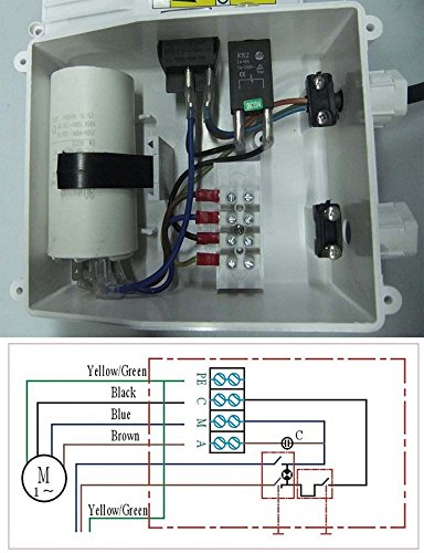
That schematic says that the capacitor is not a start cap but is a permanent run capacitor. Thus an electrolytic start cap would not work for long. The capacitor is shown active at all times. I am sorry to say that I had wrongly presumed that one of those was a capacitor timing device.
But what the heck is the device in the box with black, brown, blue wires? Is that an on-off switch?
Checking the wiring again does make sense.
I would think a 10HP gen would run a 2HP motor with no problem.
The pump motor is 1.5 kw. If it is a BACO 4SH ?
The original cap should work, It is made for that motor not a Franklin. I would double check the pump motor connections. You could have 2 wires swapped.
Good Luck.
Two hots through the switch, one through the CB, the other through the capcitor (3 legs), the last the ground straight through. I don't think it could be more simple.
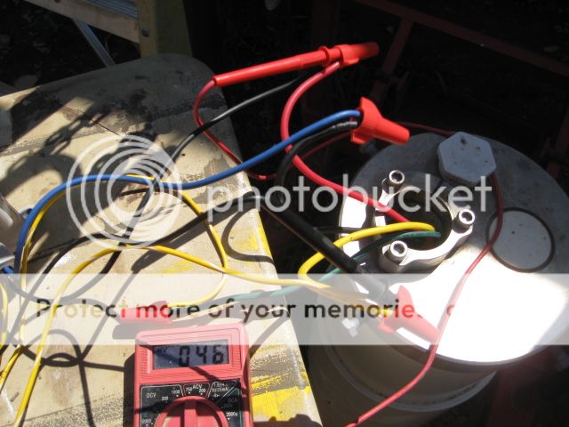
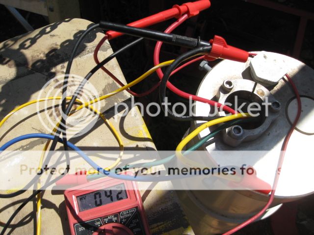
Here is my interpretation of relating the terminal strip to the schematic. The color of the letters would correspond to classic pump wire colors if my understanding is correct. View attachment 30294 As a check, with power off and motor connected, I would expect resistance from C to M to be the lowest (about an ohm plus wire round trip). Resistance C to A would be higher, and resistance M to A would be the sum of the first two readings minus one wire round trip.
Did You measure the current on the pump lines to see if the motor is working ?
I would measure the voltage across the lines, Not from ground. The voltage difference from Black and the other two wires is what matters.
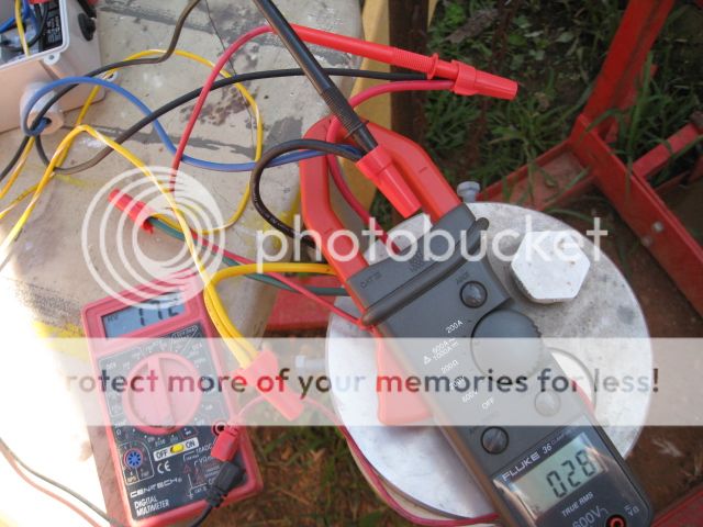
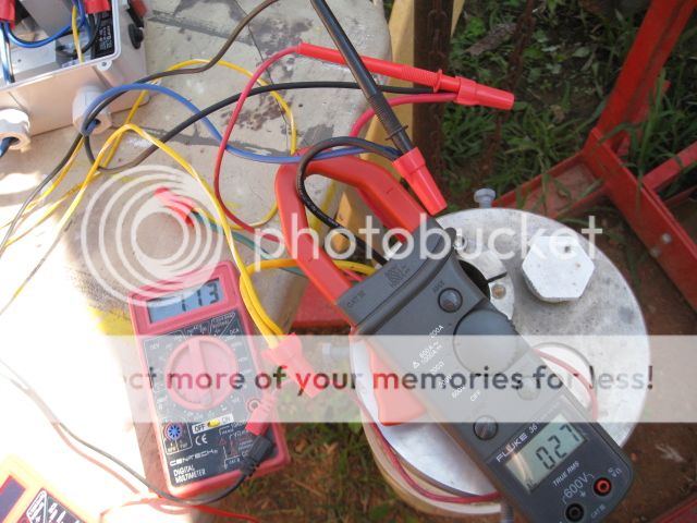
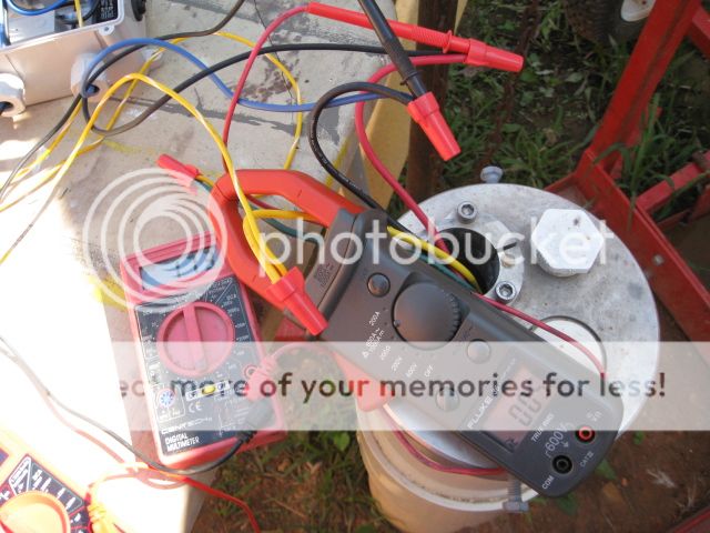
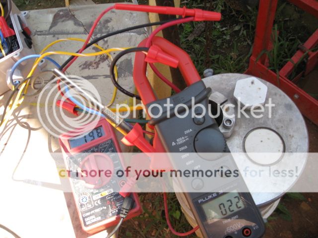
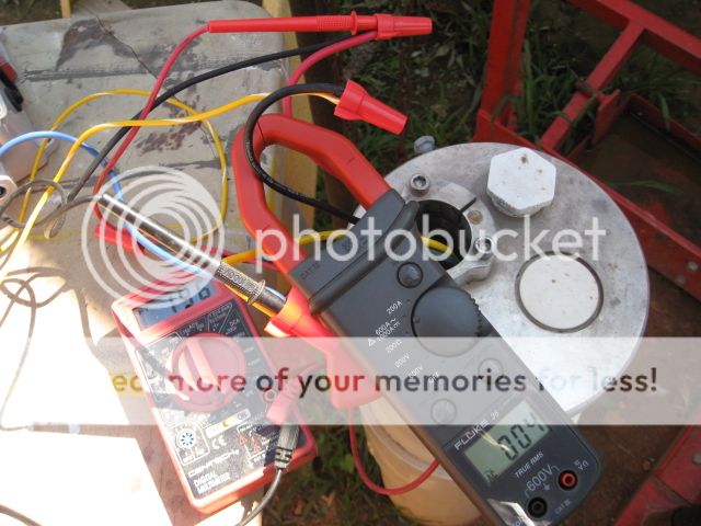
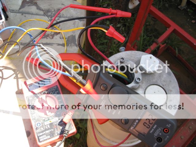
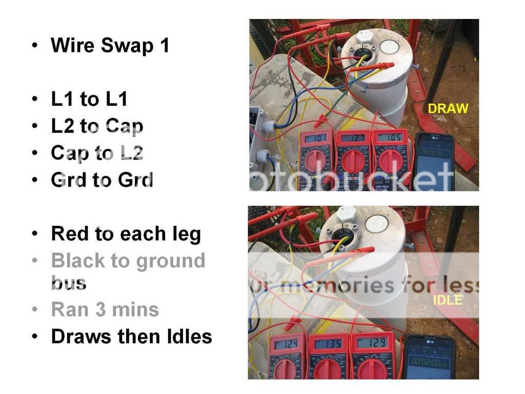
The current for L1, L2, and Cap respectively is 28, 27, and 5.
That does not add up. Is there current on the ground ?
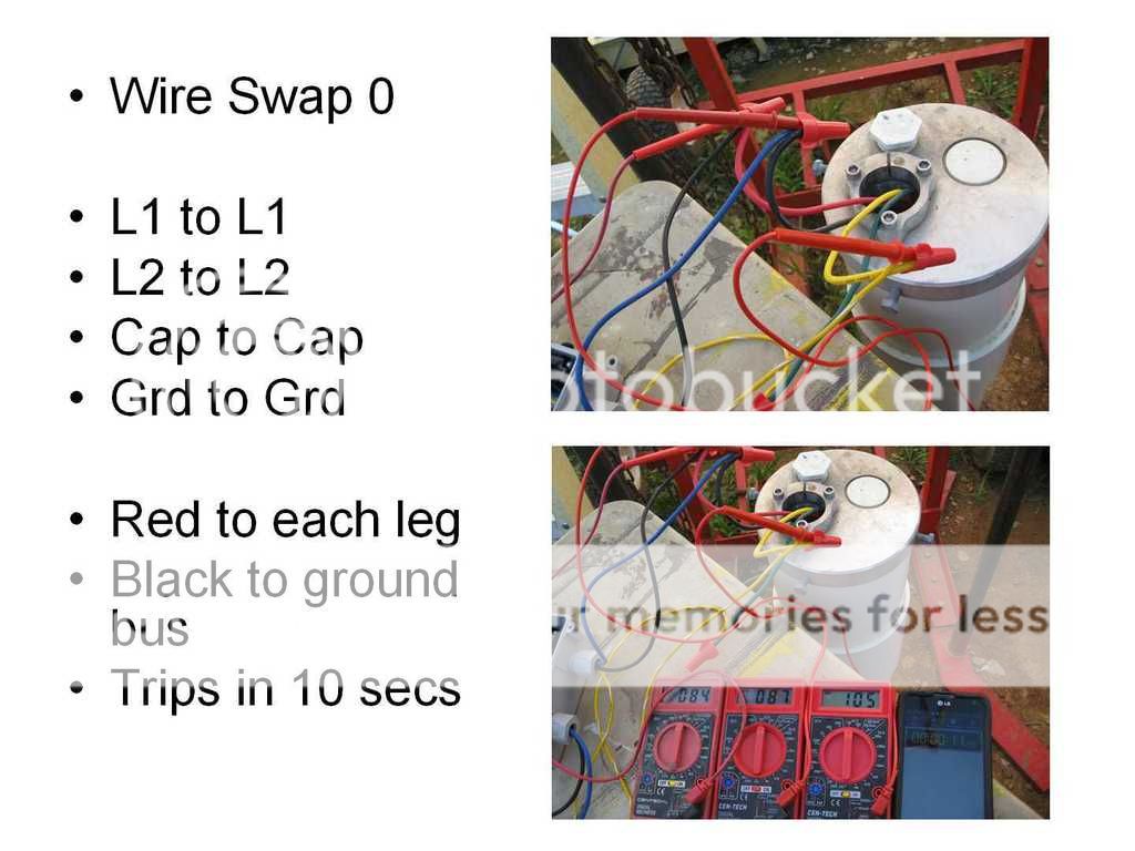
It sounds like the motor never spins up and the locked rotor protection with the 10 second reset cycles.
That cap could be bad, If it is the original, It had a old date code. I would expect that reading to be higher.
It is hard to see from here. The current is way to high. The breaker is 20 Amp.
I think the winding with the cap should have much less current than the main winding. I am not saying that 4 or 5 amps is normal, but it does not seem out of line to me considering. I think you need to try this with a bigger power source. This presumes that the voltage at the generator has dropped down and the drop is not in some long wires from the generator to the control box.It could be the Cap is bad since in either case it's only pushing 4 to 5 amps. Should it be pushing 100% like the hots or reduced since it's a run Cap?
I think the winding with the cap should have much less current than the main winding. I am not saying that 4 or 5 amps is normal, but it does not seem out of line to me considering. I think you need to try this with a bigger power source. This presumes that the voltage at the generator has dropped down and the drop is not in some long wires from the generator to the control box.
This is awkward, but...
It looks like you're using an ad blocker. We get it, but (1) terrylove.com can't live without ads, and (2) ad blockers can cause issues with videos and comments. If you'd like to support the site, please allow ads.
If any particular ad is your REASON for blocking ads, please let us know. We might be able to do something about it. Thanks.