Smoke Test: no smoke, but no go...

Users who are viewing this thread

SteveMitty79

Member
Messages
72
Reaction score
2
Points
8
Location
Missouri
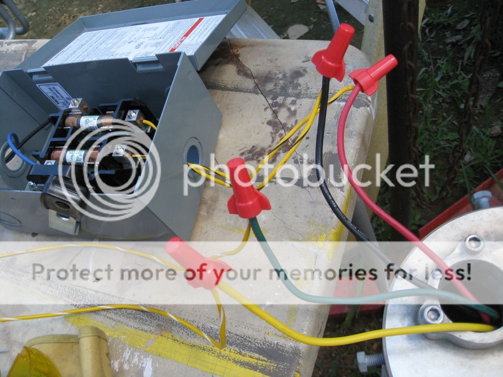
OK. I followed the wiring diagram below. I know it shows like a 110 box, but it came with the 220v pump. I just substituted the neutral for a hot so I had two power legs to the pump, one breaking off and supplying the capacitor, the third leg and finally the ground.

I fused both before the pump and the control box the main power.

It bogged down as if drawing amps for about ten seconds and the generator breaker threw. I tested again and while running, I got 127 volts each leg upside of the control box. Past the control box, I got 85 volts each leg to the pump. I wondered where the rest went, so I tried it again and found the capacitor line to the pump reading 95 volts.

No smoke but no go. Any ideas?


Last edited by a moderator:

Reach4

Well-Known Member
Messages
38,862
Reaction score
4,430
Points
113
Location
IL
When you measure a voltage, you measure between two points. In a couple of cases, you seemed to be measuring from the red pump wire, then the black pump wire, and then the yellow pump wire "to the pump". What do you mean "to the pump"? Are you measuring to the case of the pump?

When you measured 127 VAC, that was from an AC hot line to where?
 

SteveMitty79

Member
Messages
72
Reaction score
2
Points
8
Location
Missouri
When you measure a voltage, you measure between two points. In a couple of cases, you seemed to be measuring from the red pump wire, then the black pump wire, and then the yellow pump wire "to the pump". What do you mean "to the pump"? Are you measuring to the case of the pump?

When you measured 127 VAC, that was from an AC hot line to where?

I measured where the cord ties to the first switch box at the terminals. Each read 127 volts. I grounded at the bus bar in that switch box. That's before it ties into the control box. I then measured the terminals at the same point in the second switch box after the control box, but grounded to the bus bar at the first switch box since the ground ran straight to the pump from there. Each hot read 85 on the switch box terminals after the control box.

So...127 before the control box two hots, then 85 volts after the control box two hots, but with capacitor line reading 95 volts. 254 total volts before the control box two hots, 265 total volts after the control box two hots and start capacitor line.
 

Reach4

Well-Known Member
Messages
38,862
Reaction score
4,430
Points
113
Location
IL
Where was the black probe of your voltmeter?
 

SteveMitty79

Member
Messages
72
Reaction score
2
Points
8
Location
Missouri
Where was the black probe of your voltmeter?

Always on the same place, the bus bar where the green ground from the cord tied into the first switch box. Whether I was reading the red probe on the hot terminals there or at the hot terminals at the second switch box.

I was trying to determine the voltage before and after the control box. The terminals at the switches were easy access. The ground where the cord connected seemed logical.
 

Reach4

Well-Known Member
Messages
38,862
Reaction score
4,430
Points
113
Location
IL
Gotcha. So the voltage from the generator is high, but within norms.

When measuring the voltage to the pump main winding, you want the black probe hooked to the yellow pump wire terminal. Then you want to look at the black wire with the red lead.

The current for the start winding comes via the capacitor and a relay that opens after the motor starts. To measure the voltage across the start winding you would put the black probe on the yellow wire an the red probe on the blue red wire . I don't know what to expect that voltage to be. Maybe somebody does. Measuring the current might be informative, but I don't know what to expect that current to be either.

I suspect your control box does not have a big enough capacitor (yours is 65 microfarads) to start a 1.5 HP motor. But I am not sure.

The meter probes are interchangeable for AC, but I chose arbitrarily.
 
Last edited:

DonL

Jack of all trades Master of one
Messages
5,205
Reaction score
72
Points
48
Location
Houston, TX
I think you may have the Black wire on the pump swapped with Yellow.

It looks like the black wire should go to the cap on the 3 wire Flotec pumps. ? Their docs are a bit unclear.

If you are not using the Netural, you should measure across the lines, not Each to ground, because the ground on that generator may be floating.

I would verify your fuses are still good.

That was a nice setup and video. Nice job.

Good Luck.
 
Last edited:

SteveMitty79

Member
Messages
72
Reaction score
2
Points
8
Location
Missouri
When measuring the voltage to the pump main winding, you want the black probe hooked to the yellow pump wire terminal. Then you want to look at the black wire with the red lead.

The current for the start winding comes via the capacitor and a relay that opens after the motor starts. To measure the voltage across the start winding you would put the black probe on the yellow wire an the red probe on the blue wire. I don't know what to expect that voltage to be. Maybe somebody does. Measuring the current might be informative, but I don't know what to expect that current to be either.


Main winding measurement, black probe to yellow flotec wire and red probe to black flotec wire: 175 volts.

Start winding, I'm confused. Keep the black probe on the yellow flotec wire, but then the red probe on the "blue." The flotec colors are red, black, yellow and green. The yellow is the capacitor, green is ground.

Pic below. Please clarify, so I can get you that measurement. Where do you want the probe instead of blue?

IMG_4590.jpg


Slide2.jpg
 

SteveMitty79

Member
Messages
72
Reaction score
2
Points
8
Location
Missouri
I suspect your control box does not have a big enough capacitor (yours is 65 microfarads) to start a 1.5 HP motor. But I am not sure.

I think you may be right. Looking at start capacitors online, I find the 65uf suitable for 1/2 to 3/4 hp motors.

The 1 to 2 hp motor capacitors range from 105-126 uf:


So I have a 65uf start capacitor trying to spin a 2 hp motor. Is that why is starts to bog down the genny and draw amps for about ten seconds but then trips a breaker?
Can someone chime in on this please?
 
Last edited by a moderator:

Reach4

Well-Known Member
Messages
38,862
Reaction score
4,430
Points
113
Location
IL
Pic below. Please clarify, so I can get you that measurement. Where do you want the probe instead of blue?
Red. I messed up, and I have edited my post above.

Main winding measurement, black probe to yellow flotec wire and red probe to black flotec wire: 175 volts.
I think that is too much drop. I think the pump is going to want something over 200 volts. I would try to identify where that drop is coming from.

Also, fuses are not normally placed after the control box. If one fuse from your photo blows, and the other continues to deliver power, I suspect bad things could happen.
 

SteveMitty79

Member
Messages
72
Reaction score
2
Points
8
Location
Missouri
Red. I messed up, and I have edited my post above.


I think that is too much drop. I think the pump is going to want something over 200 volts. I would try to identify where that drop is coming from.

Also, fuses are not normally placed after the control box. If one fuse from your photo blows, and the other continues to deliver power, I suspect bad things could happen.

OK. I tested the start winding as you prescribed and got only 47 volts. Twice.

So to recap, 175 volts for the main, 47 for the start.

Since the start test measures the capacitor voltage, being it is way underrated, I think it wise to upgrade it to the correct range before further testing. I can acquire one post haste from the local electric supply store, 2hp, 220vac, 130uf.

Should I proceed with that?
 

Reach4

Well-Known Member
Messages
38,862
Reaction score
4,430
Points
113
Location
IL
Or would you be better served to get a whole Franklin control box? I know that would feel painful. I have lost track of how far your generator is from the well head. Closer is better. If there is separation, I think it would be best to have the control box near the well if practical if distances are long. Note that if you wire capacitors in parallel, the capacitance adds.

I also note that the Franklin AIM manual suggests a 7.5 HP 9.4 KVA generator for a 3-wire 2 HP motor.
 
Last edited:

DonL

Jack of all trades Master of one
Messages
5,205
Reaction score
72
Points
48
Location
Houston, TX
Since the start test measures the capacitor voltage, being it is way underrated, I think it wise to upgrade it to the correct range before further testing. I can acquire one post haste from the local electric supply store, 2hp, 220vac, 130uf.


You do not want a 220v cap, It will not last long. 370 or 440v is better.

Do you have a Clamp Around amp meter ?

You are measuring AC, So the probe color does not mater.

If the cap in the box is 220V, It is made for 120v. p-p applies on the cap rating.

The relay is different also. It needs to match the pump load.

Good Luck.
 
Last edited:

SteveMitty79

Member
Messages
72
Reaction score
2
Points
8
Location
Missouri
You do not want a 220v cap, It will not last long. 370 or 440v is better.

Do you have a Clamp Around amp meter ?

You are measuring AC, So the probe color does not mater.

If the cap in the box is 220V, It is made for 120v. p-p applies on the cap rating.

The relay is different also. It needs to match the pump load.

Good Luck.

Thank you Don. I wasn't ignoring you. I didn't want to lose my train of thought with Reach. I got the higher capacitor and saw the 370s, but stuck with the 250v. And that went up in smoke, so maybe for the better.

I have a video loading, so I will post it soon.
 

SteveMitty79

Member
Messages
72
Reaction score
2
Points
8
Location
Missouri
Or would you be better served to get a whole Franklin control box? I know that would feel painful. I have lost track of how far your generator is from the well head. Closer is better. If there is separation, I think it would be best to have the control box near the well if practical if distances are long. Note that if you wire capacitors in parallel, the capacitance adds.

I also note that the Franklin AIM manual suggests a 7.5 HP 9.4 KVA generator for a 3-wire 2 HP motor.

Yeah, I'm open to the idea of getting a "real" control box. Any faith I had that this could work has quickly diminished into "it's a chinese piece of plastic crap."

Here are the latest findings:


SteveMitty79

Member
Messages
72
Reaction score
2
Points
8
Location
Missouri
You do not want a 220v cap, It will not last long. 370 or 440v is better.

Do you have a Clamp Around amp meter ?

You are measuring AC, So the probe color does not mater.

If the cap in the box is 220V, It is made for 120v. p-p applies on the cap rating.

The relay is different also. It needs to match the pump load.

Good Luck.

Why are the higher capacitor voltages better and if it's marked 220, why is it made for 120? Yes, I do have a clamp meter.
 

Reach4

Well-Known Member
Messages
38,862
Reaction score
4,430
Points
113
Location
IL
Capacitor voltages are related to breakdown voltage.

There are different capacitor voltage ratings. 240 VAC is RMS voltage. If you had that voltage with no voltage spikes, the instantaneous voltage rises to 1.414 time 240. Also, the voltage can rise higher than the nominal voltage. The breakdown voltage is the highest number you might see marked for a conventional DC capacitor. The working voltage is a lower number to account for margin. I don't know how well capacitors are marked. I had presumed you had bought a capacitor made for use as a well pump starting capacitor for a 240 ("230") volt pump.

And there are different kinds of capacitors. The kind usually used in a well pump starting capacitor is a non-polarized electrolytic capacitor. It is really two regular electrolytic capacitors in series. That is because a regular electrolytic capacitor can only be used for direct current and not alternating current. If you use a regular electrolytic capacitor for AC, the capacitor will fail. Electrolytic capacitors rely on a thin oxide formed on a metal foil to serve as insulation between the foil and the conducting liquid/gel. If much current goes the wrong way, the oxide will break down and pass current.
 

DonL

Jack of all trades Master of one
Messages
5,205
Reaction score
72
Points
48
Location
Houston, TX
Why are the higher capacitor voltages better and if it's marked 220, why is it made for 120? Yes, I do have a clamp meter.

Because it is AC the P-P value for 120V is 120 X 1.414 or 169.68V p-p. Then it is good to add some overhead, so they use a 220V cap for a 120V Controller, And that is what you have.

You can measure the current of the start winding to see if it stuck in run.

And measure run current to see is it ever comes up to speed.

Good Luck.

I was slow to type, Reach4 is fast, and correct.
 
Last edited:

SteveMitty79

Member
Messages
72
Reaction score
2
Points
8
Location
Missouri
there are different kinds of capacitors.

And that's as far as I got. It's Greek to me and ironically, I'm half Greek and I still don't get it. That said...

The control box came with the pump. After conferring with Baco Eng., which sells the same pump, they said it would work directly except for the plug. The capacitor that came with it is 65uF/220v.

I found their product page online and the spec there says the capacitor is 45uF/450v. I don't know how much of a difference that makes. I may be crying over spilled milk.

2hp Submersible Pump 4'' Deep Well 220v Stainless Steel 528ft Max with 33ft Cord

So, would any different capacitor work at this stage or should I anticipate an entirely new control setup?

If so, I would like to buy a control box that would work with this existing pump as noted in the link above and is also compatible with a reasonably priced 2hp/220v pump of decent repute in the event this china pump is shot.

Any other thoughts would be helpful if bystanders would like to chime in.
 
Last edited by a moderator:
Top
Hey, wait a minute.

This is awkward, but...

It looks like you're using an ad blocker. We get it, but (1) terrylove.com can't live without ads, and (2) ad blockers can cause issues with videos and comments. If you'd like to support the site, please allow ads.

If any particular ad is your REASON for blocking ads, please let us know. We might be able to do something about it. Thanks.
I've Disabled AdBlock    No Thanks