Sizing ducts

Users who are viewing this thread

Hidden 1

Member
Messages
78
Reaction score
0
Points
6
Location
TN
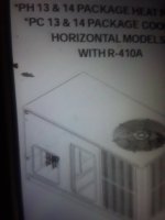
I replaced the 2 ton carrier heat pump package unit with a 2 ton goodman an had a few questions on duct sizing.
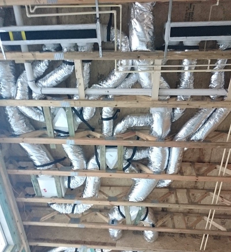
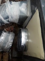
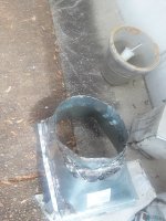
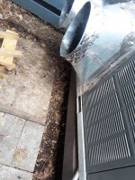
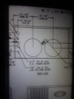
The old 50s model had 14 inch ducts on unit then a reducer at duct to 12 inch flexable thru home.It had same size on return
Is that duct downsizing supposed to happen from 14 to 12?
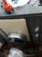
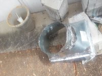
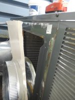
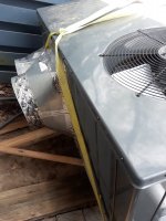
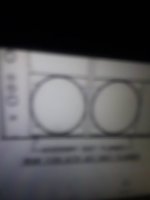
Also the new unit has a bigger base return area with a 14 in an out ,will this cause any trouble an can i use the reducers again ?
I dont want any issues with airflow an i had to change the base on return so vent could be low enough to position unit where crawlspace opening is.
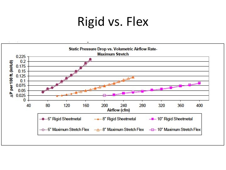
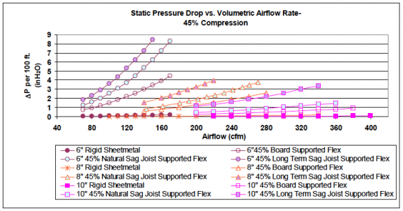
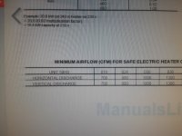
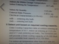
Do i need to look at the charts for cfm?
Any info is appreciated
You can see return is taller on new one.Old return an deliver were side by side both low,in diagram.
 

Attachments

  • 20180418_122017.jpg
    20180418_122017.jpg
    83.7 KB · Views: 215
  • 20180418_111623.jpg
    20180418_111623.jpg
    140.1 KB · Views: 217
  • 20180424_094856.jpg
    20180424_094856.jpg
    44.3 KB · Views: 255
  • 20180424_094913.jpg
    20180424_094913.jpg
    23.9 KB · Views: 228
  • 20180424_095631.jpg
    20180424_095631.jpg
    35.7 KB · Views: 253
Last edited:

Dana

In the trades
Messages
7,889
Reaction score
509
Points
113
Location
01609
The real answer would only come from an ACCA Manual-D design review of the duct system. For very short runs dropping duct size isn't too big a deal, but for longer runs it can be.

Aluminum tape isn't really adequate for long term reliable air seal when exposed to the elements, but it's fine when applied to shiny-clean galvanized that's fully indoors. Duct mastic can work in more exposed environments though. The slip joints and seams of the adjustable ells will leak a lot of air unless sealed with mastic too.

Flex duct that isn't pulled tight and straight has much higher than advertised duct impedance, which could be an issue if the ducts are both narrower than the and saggy/bendy. At maximum stretch flex is comparable to hard-piped duct:

slide27.jpg

But if it looks like a can o' worms or ball o' snakes, not so much:

flex-duct-static-pressure-air-flow-losses-45-percent-compression-584x306.png


joy-of-flex-800.jpg

air-diffusion-council-flex-duct-installation-standards-2-friction-rate-compression-gba.jpg


Duct leakage can be a huge efficiency hit for the system, so it's important to seal every seam in the hard-piped ells & duct boots that you can get to. But it's also important to bear in mind that sometimes with undersized ducts that duct leakage is the only thing keeping the flow high enough to avoid an iced-up cooling coil. So it's worth ensuring that the pre-existing flex is as short and straight-stretched as possible. Where it must turn, the bend radius/throat of a 12" flex should be at least 12" to keep the "equivalent feet" of duct for the turn from getting out of hand.
 

Hidden 1

Member
Messages
78
Reaction score
0
Points
6
Location
TN
Thanks..
So from that chart since i have flex under home but not at unit do i use flex chart.?

An do a lot of systems decrease the sizing at duct to unit or do most remain the exact same size as whats coming out ?
Looks like new systems are building the returns bigger than other side.
I removed that bigger return part an made a return thats directly beside other duct for a straighter direct flow,I plan to use mastic or that clay stuff,which is best?
But my biggest question is will changing that trunk out so duct is lower restrict the return to the point ill have problems?
Ill send pic .
22inches by 14 is size ..an ill cover it all but 14inch return collar.
Thanks much for all your information
 

Dana

In the trades
Messages
7,889
Reaction score
509
Points
113
Location
01609
If the ducts are flex with only short runs of hard pipe at the unit treat the whole thing as flex.

Most will run at the same size as the unit at least for the first part of the plenum, then reduce the trunk sizing as branches take off, but a good duct designer can figure out when you can get away with constricting it right out of the box. Both the supply and return duct friction matter.

I'm not sure what "...that clay stuff..." refers to.
 

Hidden 1

Member
Messages
78
Reaction score
0
Points
6
Location
TN
Its called duct seal.
Looks like green clay .
I installed a fabricated opening from sheet metal an used duct seal that comes in a tub .Do you see any issues of changing that part out ?
As in Cfm,etc?

Pic shows one removed an the fabricated one .
 

Attachments

  • 20180425_145822.jpg
    20180425_145822.jpg
    74.9 KB · Views: 232
  • 20180425_145834.jpg
    20180425_145834.jpg
    85.1 KB · Views: 226
  • 20180424_114431.jpg
    20180424_114431.jpg
    117.7 KB · Views: 252
  • 20180424_114433.jpg
    20180424_114433.jpg
    112.2 KB · Views: 239
  • 20180425_150101.jpg
    20180425_150101.jpg
    76.7 KB · Views: 213

Hidden 1

Member
Messages
78
Reaction score
0
Points
6
Location
TN
Its called duct seal.
Looks like green clay .
I installed a fabricated opening from sheet metal ,screwed in an used duct seal that comes in a tub .Do you see any issues of changing that part out ?
As in Cfm,etc?

Pic shows one removed an the fabricated one .
 

Hidden 1

Member
Messages
78
Reaction score
0
Points
6
Location
TN
Found old cfm was 800.
Looks like new is 875
But external static 1275..
Is this a issue?
 

Attachments

  • 20180424_125636.jpg
    20180424_125636.jpg
    72.2 KB · Views: 222
  • 20180424_125026.jpg
    20180424_125026.jpg
    38.5 KB · Views: 251

Dana

In the trades
Messages
7,889
Reaction score
509
Points
113
Location
01609
This is a bit outside of what's comfortable using a "design by web-forum" approach. It's probably time to either consult a local duct designer, or hook it all up and run some tests. With a dual manometer, running just the air handler (not the compressor) you can figure out if the static pressure across the air handler is within spec measuring at holes drilled in the supply & return side reducers near the air handler.

There is probably a spec for the maximum pressure difference spelled out somewhere in the documentation. Typically they're designed to function at a nominal ~0.5" water total pressure drop, but there is usually a maximum as well. (A dirty filter can be inserting as much as 0.5" drop just at the filter.) The flow at 0.7" is typically only 75% of what it is at 0.5", and it drops rapidly above that. Ideally the ducts themselves would be contributing no more than 0.1"of drop, which gives some headroom for accommodating the potential pressure drops across a dirty filter, the AC coil, furnace heat exchanger, etc. without blowing over the specified max.

If you're measuring under the max specified limit it'll be safe to run the AC, but if it's over the limit by very much there's a high risk of icing up the coil, or even worse- liquid refrigerant going back to the intake side of the compressor, which can damage it.

There are dozens youtube videos explaining how to use a manometer to measure static pressures in ducts & air handlers. Watch several until you're comfortable that you understand what you're doing. It's not rocket science, but it's shocking how many HVAC pros installing this stuff are still clueless about how to use a manometer when commissioning a new installation, or to debug an existing system, just doing it all by rules of thumb and (sometimes misleading) charts.
 

Hidden 1

Member
Messages
78
Reaction score
0
Points
6
Location
TN
I did find the specs.
Old unit had 800 cfm new has 825
Will that make much of a difference?

Going to get the static pressure an cfm tested by tech.
What all should i get tested in detail ?
 

Dana

In the trades
Messages
7,889
Reaction score
509
Points
113
Location
01609
Let this guy walk you through the basic commissioning of a new duct & air handler configuration. (Keep a pad handy and write up a list.) Any time you make changes to the system it's worth really re-commissioning it, testing everything, writing it down and keeping a copy for future reference,

If you haven't already, air-seal all seams in the register boots with duct mastic, and seal the registers to the floor/wall/ceiling material with polyurethane caulk (not cheap stuff like painter's caulk), and/or can foam (if it's a big gap) before running the static pressure tests. Any flex duct that can be stretched a bit tighter or better supported for less droop makes a difference too.
 
Top
Hey, wait a minute.

This is awkward, but...

It looks like you're using an ad blocker. We get it, but (1) terrylove.com can't live without ads, and (2) ad blockers can cause issues with videos and comments. If you'd like to support the site, please allow ads.

If any particular ad is your REASON for blocking ads, please let us know. We might be able to do something about it. Thanks.
I've Disabled AdBlock    No Thanks