Replacing existing single pole bathroom fan switch

Users who are viewing this thread

Wen72

New Member
Messages
25
Reaction score
0
Points
1
Location
Montreal
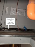
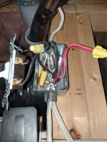
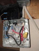
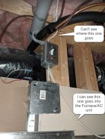
This reminds me that every time I turn on the humidistat, I can hear a clicking sound on the other side of the ceiling. I checked again in the ceiling where the clicking sound comes from, I see there is a switch marked as "Furnace" and below the switch there is a junction box marked as "Relay shutter". It is that "Relay shutter" junction box that was making the clicking sound when humidifier turns on and off.

On the Furnace switch, there is one cable (I think it is a 3-conductor) feed-in from top, looks like the power-in. There are two cables going out (I think that is the direction), one 2-conductor goes into the bottom of the Furnace unit. the other 3-conductor connects to the Relay Shutter junction box.

There are two wires going out from the Relay Shutter, one red and one white that are part of a brown cable. Cannot see where the brown cable goes. Not sure if it connects to the humidifier unit somewhere in the ceiling?

By the way, a separate topic. I think I maybe wrong when I say the Furnace/AC unit, it could be just the Furnace. We have a cooling fan unit for A/C on the roof top.

Whether we can figure it out or not, I do very appreciate your patient and time spent already walking me through this wiring maze.

Cheers,
Wen
bathroom ceiling 2.jpg bathroom ceiling 3.jpg bathroom ceiling 1.jpg
 

wwhitney

In the Trades
Messages
6,557
Reaction score
1,841
Points
113
Location
Berkeley, CA
The plot thickens. That 3-conductor cable leaving the top of the switch box is likely our missing 3-conductor end.

I think the next step is to open up the furnace shut off switch (whose box looks a bit small, I would take care to note how it is packed so you can put it back together) and the relay box below and diagram their connectivity. It would also be nice if you have a way to figure out which of the 4 ends of the 3 conductor cables are the same cable: we have furnace switch box, humidistat, fan switch, and fan itself. E.g. if you can physically see one of the cable and infer from where it disappears where it is headed. But it's OK if that's not possible, we may be able to infer.

I'm still hopeful that with the above info we can figure out what's going on, but I would say it's around 50/50.

Cheers, Wayne
 

Wen72

New Member
Messages
25
Reaction score
0
Points
1
Location
Montreal
ok, will do that tomorrow.

I also noticed that if I turn off the furnace switch, the humidistat still works. But yeah, we should be able to see how it is wired inside the furnace Switch and the relay box.

Thanks,
Wen
 

Wen72

New Member
Messages
25
Reaction score
0
Points
1
Location
Montreal
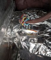
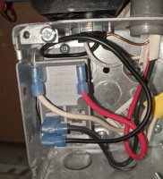
I've opened furnace switch box and the relay shutter box, took pictures of both. The furnace switch box wiring drawing is in the below full diagram. Looking at the direction where the cables disappear I had to guess where it might go, but it's pretty much matching where we thought it is going.

With this, the 4 ends of the 3-conductor are completed. Fan junction box is unknown. The 2-conductor in the fan switch and the 2 2-conductor in the humidistat junction box are also open ended.


full diagram.jpg


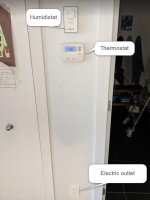
Don't know if those 2-conductor matter or not. I was wondering if it connects to something below as there is a thermostat and a electric outlet below the humidistat (pictured below). I opened the thermostat, there are black, white, red, green and yellow wires behind, so doesn't seem to have any connection to the 2-conductor in the humidistat junction box. I also tested to see if the furnace breaker affects the electric outlet below, it did not. It operates normally (with electricity when the furnace breaker is off).

furnace switch box.jpg relay shutter.jpg humidistat.jpg

Thanks,
Wen
 

wwhitney

In the Trades
Messages
6,557
Reaction score
1,841
Points
113
Location
Berkeley, CA
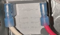
A thermostat is typically low voltage, you can see the other end of the thermostat wire in your second picture from yesterday, those blue wire nuts under the furnace are the connections between the thermostat wire and the furnace. Since it's low voltage, it doesn't need a box.

Your diagram is a very nice presentation of the data we have. The cable connectivity you've drawn in is plausible. If I had to guess, I'd say one of the 2-conductor cables at the humidistat is the feed from the electrical panel, and the other is the outgoing feed to the fan switch box.

I need to ponder the possibilities a bit more. It is likely that if you use a motor rated mechanical timer (that goes tick tick tick), you can just connect it up in place of the switch (it has just two wires) and everything will work as it has. To correctly wire a 3-wire electronic timer will require understanding the whole circuit. At first glance, going by colors, the fan switch is switching the neutral to the fan, but that doesn't make sense, since the fan still operates via the dehumidistat even with the switch off.

Getting a diagram of the fan junction box would be a big help, but I'll see what I can deduce with out it. Have you checked if the drywall box looks openable? For example, if the top piece of drywall is only held on by screws going through exposed metal angles like in your photo, one could unscrew them all and remove the top piece to get to the junction box.

This has been quite the circuit tracing project.

Cheers, Wayne
 

Wen72

New Member
Messages
25
Reaction score
0
Points
1
Location
Montreal
A thermostat is typically low voltage, you can see the other end of the thermostat wire in your second picture from yesterday, those blue wire nuts under the furnace are the connections between the thermostat wire and the furnace. Since it's low voltage, it doesn't need a box.
I see. Yes, there is no box behind the thermostat. The cable poke through a hole in the drywall.

Have you checked if the drywall box looks openable?
I will need a longer ladder first so I can assess if I can reach to the top of the drywall box. I do have a longer ladder, will need to get it from the storage over the weekend. Will let you know after the weekend.

This has been quite the circuit tracing project.
Would be nice if there is a drywall see-through device:)

Have a great weekend.
Wen
 

wwhitney

In the Trades
Messages
6,557
Reaction score
1,841
Points
113
Location
Berkeley, CA
I've been thinking about your circuit diagram, and I still can't figure out how the missing parts could be wired to cause it to works as described.

The best I can come up with is to hypothesize both a relay and a current sensor in the fan junction box, while seems a bit unlikely. There's also the possibility that the wiring at the fan switch isn't 120VAC, but is 24VAC, which is somewhat suggested by the labeling of the white wires "common".

If a mechanical timer is sufficient, then I would suggest that as a simple solution. An electronic timer will require constant power and normally provides its output as a switch hot. So if it's the white wires going to your fan switch are 120V neutral conductors, and the fan is controlled with a switched neutral, to make an electronic timer work would require a relay.

Cheers, Wayne

P.S. It would be interesting to know the part numbers of the box inside the "shutter relay box" and the black box mounted to the outside of it. But it might be just a sidetrack, I don't know if it would be useful.
 

Wen72

New Member
Messages
25
Reaction score
0
Points
1
Location
Montreal
So the red and white wires connect to the fan switch is similar to the way it works for the red and white wires going out from the relay box to the humidifier?

This is my first time seeing a relay, or this complicated wiring. Before moving into this condo apartment, we lived in a townhouse. As a self-taught DIYer, I was able to add a breaker in the electrical panel in the basement and ran new wirings for about 10 pot lights for our living room on the second floor. Took me a while to finish, maybe 1 year or so.. Drywalls and ceiling were all teared down and lots of complains from my wife, too:). Figured out how a 3-way switch is wired is probably the most complicated cases that I can understand for electrical wiring:) So how does a relay work and in what situation it is required?

Thanks,
Wen
 

wwhitney

In the Trades
Messages
6,557
Reaction score
1,841
Points
113
Location
Berkeley, CA
If you're comfortable using a voltmeter on a live circuit, there are more diagnostics you can do at the switch box. But if you're not familiar with doing that, I wouldn't advise making this the first time.

A relay is a just a switch that is electrically activated. Two of the connections on the relay are to the "coil" and when the correct voltage is applied to those connections, the relay changes state (some relays might have multiple coil connections for different voltages). The other connections could be as simple as two points that are normally disconnected (called normally open or NO) when the coil is unpowered and become connected when the power is applied to the coil. Or there could be two points normally connected (called normally closed or NC) when the coil is unpowered which become disconnected when power is applied to the coil. Or there could be three connections, two of which form an NO pair and two of which form an NC pair (like a 3-way switch).

So if the white and red wires to your switch are not 120V, or if the white wires are a 120V neutral, and you want to duplicate the functionality of your current switch using a 120V electronic timer, you could use a relay to do that. The electronic timer requires constant hot and neutral and provides a switched hot; the switched hot goes the coil of a 120V-coil relay, which also gets a constant neutral; and the NO contacts of the relay play the role of your mechanical switch.

But that's a bit complicated and it would difficult to fit it all in your junction box. Relay-In-A-Box provides nice prepackaged relays that mount to a knockout on an electrical box, but for that you'd need to remove some drywall and make a 7/8" diameter hole in your electrical box.

So as I see it you have a few possible options now:

1) Stick with a switch or a mechanical timer
2) Access the fan junction box, hopefully it will elucidate your existing circuit, but we may still be unsure if you've found all the wiring/boxes or of the cable end matching
3) If you are qualified, do some testing with a volt meter at the switch box
4) A relay solution

Cheers, Wayne
 

Wen72

New Member
Messages
25
Reaction score
0
Points
1
Location
Montreal
Took me some time, but I think now I have a very rough idea of how a relay works.

If you're comfortable using a voltmeter on a live circuit, there are more diagnostics you can do at the switch box. But if you're not familiar with doing that, I wouldn't advise making this the first time.
Have not use a voltmeter before..

I brought back my ladder and had a pretty good look on the drywall box in the ceiling. My conclusion is that when they install the bathroom fan and boxed the fan housing in drywalls (or in the reverse sequence), they really didn't want anyone to open it. There are two sides out of four I can't get to and there are quite some screws screwed from the inside. The drywall box was probably closed before the fan housing was installed, and if that was the case, I supposed that I should be able to uninstall the fan and then the housing in order to reach to the fan junction box. But as I checked last time, I was not able to uninstall the fan housing when I took off the fan.. Anyway, it looks like a dead end to me.

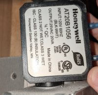
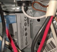
By the way, this is the pictures of the two boxes you were asking previously. One is outside of the relay shutter, one is inside.
relay 1.jpg relay 2.jpg

Am accepting that option #1 is the only option I can take. But thanks for all your valuable thoughts and suggestions. I really appreciate.

Thanks,
Wen
 

wwhitney

In the Trades
Messages
6,557
Reaction score
1,841
Points
113
Location
Berkeley, CA
Well, depending on how determined you are, there's still a little more sleuthing you could do. It would be easier if you were familiar with a voltmeter and qualified to work on an energized circuit, but the same information can be gathered without working on an energized circuit, if you are comfortable taking apart and making connections (wirenuts). You just have to turn off the circuit, setup the measurement, turn on the circuit, read the measurement, and repeat 3-10 times. Let me know if you are interested in that route.

Also, on those last two pictures--the last one, of the grey box, that looks like a relay. I don't see any identifying information in the text on the side, the more useful information is probably the embossed diagram on the front. The relay appears to control power to the 24V power supply, which is the black Honeywell box. Do you know where the two wires coming out of the side of the box go? I assume they enter a cable with a brown sheath that goes to some shutter actuator. It would be good to have confirmation, mostly that there isn't a more extensive 24V circuit that is carried by some NM cable and goes to the fan switch (not very likely).

Cheers, Wayne
 

Wen72

New Member
Messages
25
Reaction score
0
Points
1
Location
Montreal
if you are comfortable taking apart and making connections (wirenuts). You just have to turn off the circuit, setup the measurement, turn on the circuit, read the measurement, and repeat 3-10 times. Let me know if you are interested in that route.
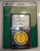
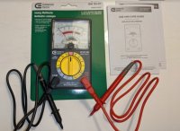
Yup, I'm comfortable making connections, eager to resolve the mystery:) I bought a Analog Multimeter today. I vaguely remembered using it to test battery when I was in junior or senior high school. I'm comfortable using it, just need some help:) It would be great if you could tell me what should I dial to, what do I need to test and which two wires in the fan switch box. I will try to read the manual tonight and maybe google a little bit on how to do the basic operation on this thing.

Do you know where the two wires coming out of the side of the box go? I assume they enter a cable with a brown sheath that goes to some shutter actuator.
Yes, it is a brown cable. It connects to the back of a insulated duct, so it should be the exit from the furnace and A/C unit. Maybe the humidifier is inside the duct?

brown wire to duct.jpg embossed diagram.jpg multimeter 1.jpg multimeter 2.jpg
 

wwhitney

In the Trades
Messages
6,557
Reaction score
1,841
Points
113
Location
Berkeley, CA
So, if you want to take measurements without interacting with a live circuit, you'll need two more things. One is some alligator clip ends for your multimeter probes. I think they make some that friction fit over the end of the probe, with an insulating sleeve that slides down over that connection. [Or you could use some short leads with alligator clips on both ends, but that would leave more exposed metal in the circuit.]

The other thing you'll need is 2 lengths of solid #14 insulated wire with stripped ends (pigtails), so that you can turn off power, remake 1 or 2 connections with an extra pigtail, connect your meter with the alligator clips, make sure any exposed metal in the circuit is spatially isolated, and then turn on power to read the meter.

Mostly you'll want to take AC voltage measurements. That's the V~ region to the left of OFF, and you pick the number corresponding to the largest measurement you anticipate. 50V is too low, so use 250V.

As a warm up exercise, you can take some measurements with your existing probes at a live receptacle (not tamper resistant), since it doesn't have exposed energized parts. You hold the probe away from the bare end and stick the bare end into one of the receptacle holes; you may need to angle the probe a little to make contact with the wipers inside the receptacle. The round hole is ground, the little slot is hot, and the bigger slot is neutral. If you measure them pairwise, you should find 120V L-G and L-N, and 0V N-G. For AC voltage, it doesn't matter which probe goes where; reversing the probes gives the same measurement.

Cheers, Wayne
 

Wen72

New Member
Messages
25
Reaction score
0
Points
1
Location
Montreal
As a warm up exercise, you can take some measurements with your existing probes at a live receptacle (not tamper resistant)
I tried last night, the metal tip of the probes of this multimeter I bought is too short to stick into a live receptacle! Why do they sell this kind of short probes and are they any useful? Do I have to buy a new probe or are there any adapters? Oh boy, I hope I don't have to return it and buy another..

Thanks,
Wen
 

Wen72

New Member
Messages
25
Reaction score
0
Points
1
Location
Montreal
Oops, sorry, I just realized after a quick search on the internet the short tip probes is a cap, once I took off the cap, the long probes are there.

Just tested a live receptacle, the reading is 125 V.

Thanks,
Wen
 
Last edited:

wwhitney

In the Trades
Messages
6,557
Reaction score
1,841
Points
113
Location
Berkeley, CA
So, it's worth testing all three combinations as an internal consistency check.

Then once you have the additional equipment to do this safely, the first question is what is the voltage on the white wires going to the switch, relative to (a) ground (the bare or green wires in the box) and (b) the black wires of that circuit? And also check the black wires relative to ground, again as an internal consistency check.

Cheers, Wayne
 

Wen72

New Member
Messages
25
Reaction score
0
Points
1
Location
Montreal
Am out of town this weekend, will find sometime to do the test next week. Just to make sure I understand, this is what I need to do:

1. Turn off the breaker.
2. Disconnect the white wire from the switch.
3. Connect the white wire with #14 insulated wire that I will prepare first (with both ends stripped) to make the length, clip the alligator clips to the end of the #14 insulated wire and one probe of the multimeter.
4. Connect the bare wire with another #14 insulated wire that I will prepare first as well to make the length, clip the alligator clips to the end of this #14 insulated wire and the other probe of the multimeter.
5. Turn on the breaker.
6. Read the meter.
7. Repeat Step #1 to Step #6, but in Step #4, instead of the bare wire, disconnect and connect the black wire.
8. Repeat Step #1 to Step #6, but in Step #2, instead of the white wire, disconnect and connect the black wire.

So it will give us readings on:
- White vs bare
- White vs black
- Black vs bare

Have I got that right?

Thanks,
Wen
 

wwhitney

In the Trades
Messages
6,557
Reaction score
1,841
Points
113
Location
Berkeley, CA
That's right. You need to make sure that any exposed metal at the alligator clips isn't touching anything else metal; it would be helpful to get alligator clips that have extra long insulated shields you can slide down over the connection.

Also, for the bare wire only, you can skip the pigtail, assuming you can get an alligator clip on the bare wire, and you don't have to worry about shielding the connection. So an efficient order to do the tests would be, say, white/bare ; then white/black ; then black/bare.

Cheers, Wayne
 
Top
Hey, wait a minute.

This is awkward, but...

It looks like you're using an ad blocker. We get it, but (1) terrylove.com can't live without ads, and (2) ad blockers can cause issues with videos and comments. If you'd like to support the site, please allow ads.

If any particular ad is your REASON for blocking ads, please let us know. We might be able to do something about it. Thanks.
I've Disabled AdBlock    No Thanks