Recurring air in zone or crack in heat exchanger?

Users who are viewing this thread

Al S

Engineer
Messages
61
Reaction score
2
Points
8
Location
The land of pain - NY
I have a 13 month old (Burnham ES2-3) two zone system. One zone for heat, the other feeds the Burnham 35 gallon indirect. It has to be purged very frequently. How can one determine if the cast iron may have a crack where it can take on air but not release water (if that is even possible)? There are only 2 No. 67 air vents which always release water when checked and not air. The remainder valves are manual and also never release any air. Is there anything I can do on my own to diagnose?
 

Dana

In the trades
Messages
7,889
Reaction score
509
Points
113
Location
01609
The system should be at a pressure high enough to never suck air, even at the lowest-pressure point of the system, which is the highest elevation on the system. Dynamic pressure differences due to pumping alters the pressure at different points on the system, but most 1-2 story residential systems do just fine at ~12 psi (non-pumping) at the boiler in the basement, but if it's over-pumped or there are flow restrictions that create low-pressure points on the system it may need a bit more than that. Charging the expansion tank to 15-20psi and filling the system to that pressure may be all it takes to fix the air infiltration issue if that's what's going on.

If the system is constantly losing pressure there may be a leak somewhere, or if it's leaking but being aut0-filled to pressure with an auto-fill valve that too can bring in air. If set up with an auto-fill, turn off the isolating valves to that it won't add water to the system and observe the system pressure for several days/weeks. It should stay within a fairly narrow range (relative to the system's water temperature) and not lose ground over time.
 

Al S

Engineer
Messages
61
Reaction score
2
Points
8
Location
The land of pain - NY
The gauge doesn't have much in the way of resolution but I can safely determine that it is about 14-16 PSI. I increase to > 20 PSI during a purge. The system is in a basement and the monoflo is serving one floor above it. The pressure is at about 14-16 PSI as installed. The original B&G flo valve was left in place (don't ask me why) from the original system. I have check valves on the Grundfos circulators so I wonder if leaving the B&G there may be a contributor to the issue. No signs of water ANYWHERE as far as a leak is concerned. Please explain "over-pumped" I assume I can check the pressure on the expansion tank? If so I will ensure 15-20 psi, but again the pressure gage on the boiler is about 15 psi anyway. It DOES have an autofill valve (isn't that standard?) which has the bypass lever that I use to increase pressure for purging. The zone has a shut-off and drain valve pair for each zone so I am guess that is what is meant by isolating valve. If so, I would have to then shut off the ball valve for the zones and then watch for a pressure change. Please confirm. Also the installer didn't put in a air scoop/scrubber

BTW. Thanks so much for the advise. I was expecting a dissertation from some of why I should have not installed what I have in the first place.
 

Dana

In the trades
Messages
7,889
Reaction score
509
Points
113
Location
01609
The expansion tank has to be pre-charged to the desired system pressure before pressurizing the system or it may not have sufficient expansion capacity to accommodate the changes in water volume from when the system is cool to when it's at full temp. To bring the system up to pressure you'll have to adjust the auto-fill valve to fill to a higher pressure or use the quick-fill lever on the top of the auto-fill while keeping an eye on the gauge.

By "over pumped" I mean that the pump is ridiculously oversized for the plumbing/flow that it's driving, resulting in a much higher than usual pressure difference between it's intake and output side, making a very-low pressure location on the system.

Auto-fill valves are standard for new boiler-installations, but they are something of a "solution problem", trading one set of problems (low system pressure, should there be a leak somewhere) for another (high system pressure when the auto-fill valve seats wear out or get a piece of grit in them causing seepage until the system is at the same pressure as the potable water system.) If you turn off the boiler filling branch completely with the isolating valve once the system is filled & pressurized it's fine. The system will let you know if the pressure is falling low long before low water becomes a safety problem. It starts with a bit of sizzle at the boiler, and as the pressure drops furner it becomes a lot of banging commotion coming from the boiler & system. The noise occurs when what is normally micro-boil on the heat exchanger plates starts becoming macroscopic, with bubbles forming then collapsing suddenly when the flow moves the bubble away from the heat exchanger plate. When the bubbles are still pretty tiny it's just a sizzle, but as the bubbles get bigger at even lower pressure, it's as loud as if someone were banging on the pipes.

There's nothing wrong with the ES2-3 boiler or a 35 gallon indirect. Most people install something ridiculously oversized to match the ridiculous oversizing of whatever preceded it.
 

Al S

Engineer
Messages
61
Reaction score
2
Points
8
Location
The land of pain - NY
Is it possible to create a large pressure difference by having the original B&G Flo valve downstream of the circulator pump? The Grundfos circ. is fairly small for what it has to push against. It is also 3 speed (don't know the model just yet). As far as noise goes. I hear the pump when it is spinning up then I hear the water moving along in the pipe from one end of the run to the end. When I purge it, it is VERY quiet. You never hear even a trickle.
 

Al S

Engineer
Messages
61
Reaction score
2
Points
8
Location
The land of pain - NY
I've attached 3 views of the header, pumps and relevant plumbing. Though not seen from these pics. There is the original flow valve which is downstream of the 1 inch pipe that goes upward to the top right of first pic
 

Attachments

  • DSCN1065.JPG
    DSCN1065.JPG
    102.2 KB · Views: 348
  • DSCN1066.JPG
    DSCN1066.JPG
    113.6 KB · Views: 304
  • DSCN1068.JPG
    DSCN1068.JPG
    107.9 KB · Views: 308

Tom Sawyer

In the Trades
Messages
3,625
Reaction score
34
Points
48
Location
Maine
Looked at the pictures and badger mech is correct, it most certainly is a piping problem, lol but, not one that you should try to straighten out. IOW, it's a friggin mess that needs to be totally reworked from the feeds to the returns. Who did that, Stevie Wonder?
 

Al S

Engineer
Messages
61
Reaction score
2
Points
8
Location
The land of pain - NY
For what it's worth, the comment "It is certainly a piping problem..." was posted prior to posting pictures. If you can specifically suggest what is wrong with it, I would appreciate it and get the installer on it to fix it, otherwise your remarks aren't helpful.
 

Dana

In the trades
Messages
7,889
Reaction score
509
Points
113
Location
01609
Fer sher- Stevie Wonder probably doesn't even have a plumbing license! :)

I'll let BadgerBoilerMN spell it out for you in better detail, if he has the time.

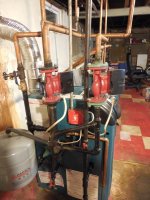
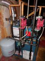
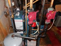
What's immediately obvious to this unlicensed practitioner is that the expansion tank needs to be between the boiler and the input side of both pumps, and not hanging out on some long branch of plumbing, so that it can work as the high-frequency shock absorber for the pump impellers, reducing cavitation.

Also, hanging the expansion tank out on plumbing like that without support will also surely cause a catastrophic failure/leak at some point due to the long moment-arm of the plumbing stressing the tee and the vibe from the pumps inducing metal fatigue. This isn't a matter of if, but of when.

As-configured the pump on the left in the pictures is getting ZERO benefit of the expansion tank, and the pump the right is getting maybe 10% of what it would be getting if expansion tank were hanging on a tee (or better yet, on an air-scoop) on a straight section of fat pipe between the boiler and pumping manifold rather than at the long end of some isolated branch.

Download the manual, and pay attention to both the details in section 6/p.12, and in Figure DW3 / p.47 in Appendix D.
 

Tom Sawyer

In the Trades
Messages
3,625
Reaction score
34
Points
48
Location
Maine
It would take too much time to explain just how screwed up the piping is and more importantly, what's the point? As I said, it needs to be taken back to the boiler feed and return and be totally re-piped. The proper piping can be found in the instructions or in several publications such as Dan Holohans "pumping away". Or on the taco-HVAC web site. This isn't something that can be done by a handy man or homeowner. There are very specific dimensions and locations that must be followed.
 
Top
Hey, wait a minute.

This is awkward, but...

It looks like you're using an ad blocker. We get it, but (1) terrylove.com can't live without ads, and (2) ad blockers can cause issues with videos and comments. If you'd like to support the site, please allow ads.

If any particular ad is your REASON for blocking ads, please let us know. We might be able to do something about it. Thanks.
I've Disabled AdBlock    No Thanks