I'm replacing my first well pump and I am replacing an old Gould 1/2 horse convertible jet pump with a Grundfos 10s7-12 3/4 hp pump. I'd like a fitting that can hold up to the max pressure the pump can put out and maintain a nice safety margin. I intend to use at least a 200 PSI poly pipe but I cant for the life of me find a rating for the insert fittings. If I have done my math correctly then I believe the pump should be capable of pushing just under 150 PSI.
You are using an out of date browser. It may not display this or other websites correctly.
You should upgrade or use an alternative browser.
You should upgrade or use an alternative browser.
Pressure rating on insert fitting.
- Thread starter LiO
- Start date
Users who are viewing this thread
Total: 3 (members: 0, guests: 3)
Those fittings, brass or stainless steel, are able to handle pressures much higher than that. For hanging a pump, it may be worth getting the extra-long barbed fittings that can fit 3 worm-gear clamps instead of the usual 2.I'm replacing my first well pump and I am replacing an old Gould 1/2 horse convertible jet pump with a Grundfos 10s7-12 3/4 hp pump. I'd like a fitting that can hold up to the max pressure the pump can put out and maintain a nice safety margin. I intend to use at least a 200 PSI poly pipe but I cant for the life of me find a rating for the insert fittings. If I have done my math correctly then I believe the pump should be capable of pushing just under 150 PSI.
Your old 1/2 HP jet pump was almost enough. A 1/2 HP submersible is about twice as effective as a 1/2 HP jet pump. A 10 GPM 1/2 HP pump would be more than enough for a pump 80 ft down. The 10s7-12 would be good for water that could fall to about 160 ft down.
Last edited:
Sponsor
Paid Advertisement
Thank you for the quick response. Would I also use the same kind of barbed fitting at the top of the poly pipe so I could convert over to steel pipe or is there an insert fitting that has an FIP end that would be used?
I looked at the 1/2 hp pump but I believe it wouldent quite meet the pressure I wanted. I wanted to be at 50 to 60 psi at the farthest faucet in the house. Pump would only be 40 feet down and I did include pressure loss due to friction in the pipes. The 3/4 horse seemed to be little big for my needs but as far as I could tell it would meet my requirements and be the closest to operating within the "BEP" (I believe its called)? I had a heck of a time figuring out how to read a pump curve so I could be off on that.
I looked at the 1/2 hp pump but I believe it wouldent quite meet the pressure I wanted. I wanted to be at 50 to 60 psi at the farthest faucet in the house. Pump would only be 40 feet down and I did include pressure loss due to friction in the pipes. The 3/4 horse seemed to be little big for my needs but as far as I could tell it would meet my requirements and be the closest to operating within the "BEP" (I believe its called)? I had a heck of a time figuring out how to read a pump curve so I could be off on that.
The tables are easier.
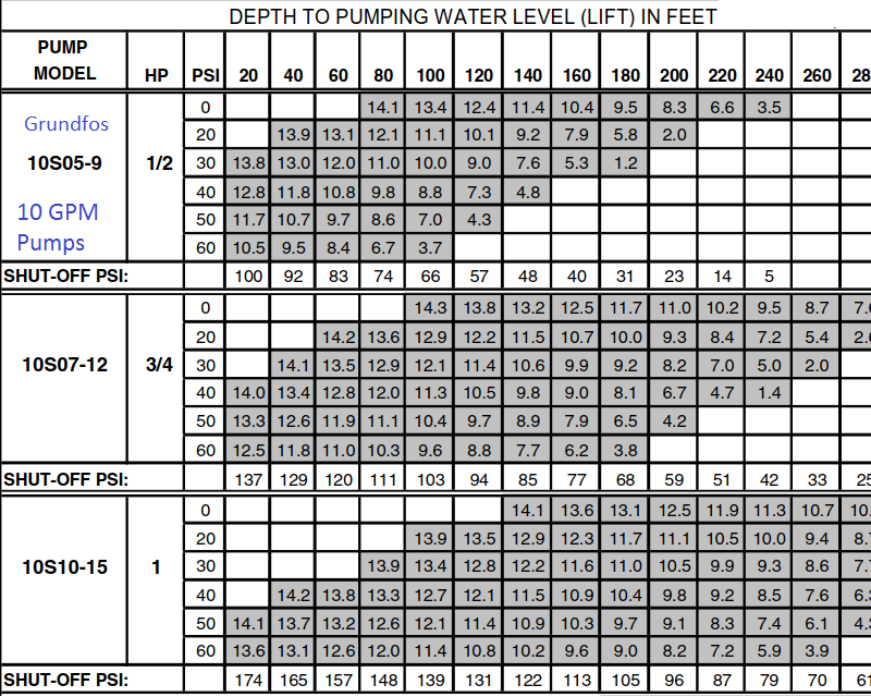
A 7 gpm pump is enough for most houses, but with your water being as shallow as it is, no need to use the more-expensive 7 gpm pump. Do use a 44 gallon or more pressure tank, unless you use a CSV.
A 7 gpm pump is enough for most houses, but with your water being as shallow as it is, no need to use the more-expensive 7 gpm pump. Do use a 44 gallon or more pressure tank, unless you use a CSV.
LOL, I dont know where you found that table, I looked all over for one for a couple weeks and all I could ever find was the pump curve. It looks like the 1/2 horse would have been fine. I do have some irrigation run off the well pump as well using just under 10 gpm at 35 PSI. I was originally going to put in a 16 GPM 1 hp pump. Glad I didn't listen to our pump guy here. I did want to use a CSV and the extra long insert fittings. I also wanted to put in an 86 gallon tank or two further down the road. But those would mostly be for water storage when the power went out. I believe I have a 15 gallon tank now. Wont a CSV make the pump run at max pressure once all the water is turned off and its re-pressurizing/filling the pressure tank up to the cut off point? I believe I read something about it allowing 1 GPM though once it has his the set pressure.
This time I found it at https://terrylove.com/forums/index.php?threads/new-well-how-much-gpm-should-i-need.66390/
I copied sections of a Grundos book to make it.
If you want to irrigate, tune your irrigation load to match what the pump can do.
Do put a flow inducer sleeve on your pump. You will find descriptions of that in this forum.
I copied sections of a Grundos book to make it.
If you want to irrigate, tune your irrigation load to match what the pump can do.
Do put a flow inducer sleeve on your pump. You will find descriptions of that in this forum.
It is almost impossible to "tune your irrigation load to match the pump". That is one of the things a CSV does for you. With a 10S07-12 there will be a max pressure of 147 PSI on the pipe when using a CSV. An 86 gallon tank only holds 20 gallons of water. And you cannot count on that 20 gallons as storage. With a 40/60 pressure switch you can never be sure how much or how little water is in a pressure tank when the power goes off. Murphy's law says the pressure will be at 41 when the power goes off, and those two huge tanks will only have about 2 gallons stored for you to use. With a CSV you only need a 4.5 or a 10 gallon size pressure tank. If you want water when the power goes off, put a couple of 5 gallon sealed jugs in a closet, or get a generator to run the pump when there is no power.
When I initially designed my irrigation system I did so with the intention of putting a larger pump in. My goal was to keep the pump pumping water while the irrigation was on so the pump wouldent cycle. Its a little bigger than the current pump can handle. I'll probably need to do some tweaking once the new pump gets in just due to higher pressure than its running at now.
Honestly I am more concerned about the CSV potentially damaging the pump and building a flow inducer for the pump. Generator is already in the works and the old pressure tank has to be replaced as is. Previous owner used a bladder-less holding tank as his pressure tank which is fine but its not holding air very well anymore.
Honestly I am more concerned about the CSV potentially damaging the pump and building a flow inducer for the pump. Generator is already in the works and the old pressure tank has to be replaced as is. Previous owner used a bladder-less holding tank as his pressure tank which is fine but its not holding air very well anymore.
Honestly I am more concerned about the CSV potentially damaging the pump and building a flow inducer for the pump.
Then you have nothing to worry about. I don't know how many times I have said it but back pressure is good for the pump/motor. Back pressure makes the motor draw lower amps, run cooler, and last longer. As long as your pipe is good for the 147 PSI, which is nothing for most pipe, you are not going to hurt anything and it will actually make everything last longer.
As for the flow inducer, all you need is a ten dollar piece of 4" drain pipe. Like this.
Pipe I was going to use was 1" 250 psi poly. Such a high rating because partly I dont trust the quality of the box-store brands and partly because I wont have to special order it.
Seems I am going to over think this like I usually do. I would think a 4" piece of pipe over a 4" pump would restrict the intake flow too much and damage the pump. Even if the pump is 3-1/8 inch that's still not much of a gap. From what I am reading it looks like a 4" sleeve would reduce the cooling requirements to 1.2 gpm. If the csv only allows 1 gpm to fill the tank for the last bit then whats to prevent the motor on the pump from overheating. I dont see how back pressure would lower the running amps since it will be the same amount of power supplied to the motor and it will have to work harder to keep up the higher pressure. I just cant get my brain to accept that so I am missing some bit of information that allows me to see how that works. I've seem some proof that there is less wear on the pump but I still dont quite understand how that happens either.
Seems I am going to over think this like I usually do. I would think a 4" piece of pipe over a 4" pump would restrict the intake flow too much and damage the pump. Even if the pump is 3-1/8 inch that's still not much of a gap. From what I am reading it looks like a 4" sleeve would reduce the cooling requirements to 1.2 gpm. If the csv only allows 1 gpm to fill the tank for the last bit then whats to prevent the motor on the pump from overheating. I dont see how back pressure would lower the running amps since it will be the same amount of power supplied to the motor and it will have to work harder to keep up the higher pressure. I just cant get my brain to accept that so I am missing some bit of information that allows me to see how that works. I've seem some proof that there is less wear on the pump but I still dont quite understand how that happens either.
Presume the pump motor is 3.75 OD. Assume solvent weld D2729 sewer pipe (the green pipe in the photo): OD 4.215 ID 4.056
There would be an annular space of 1.876 square inches, which is more than the inside area of a 1.5 inch PVC pipe.
Schedule 40: is OD 4.500 ID 4.026. That would still leave more than enough space.
They design these pumps to be used in 4-inch PVC casing.
There would be an annular space of 1.876 square inches, which is more than the inside area of a 1.5 inch PVC pipe.
Schedule 40: is OD 4.500 ID 4.026. That would still leave more than enough space.
They design these pumps to be used in 4-inch PVC casing.
Last edited:
A 4" pump inside a 4" shroud will have a little less than a 1/4" gap all the way around. I have tested this and know it will not restrict the pump at all unless it is pumping more than 60 GPM.
The reason you are having a hard time understanding the amps drop when the pumps flow is restricted, is because it is counter intuitive. You would think restricting the flow from a pump would make it work harder, and it would if it were a piston type pump. But a centrifugal type pump works more like a blow dryer or a vacuum cleaner. When you put you hand over the suction of a vacuum cleaner or a blow dryer, you can hear the motor speed up. If you have an amp meter you can also see the amps go down. That is because the blower or pump isn't moving any air or water, and there is no load for the pump. The more GPM a pump is putting out, the more weight it is lifting. 1 GPM weighs 8.33# per minute. 10 GPM weighs 83.3# per minute, and that is what draws amps, not the pressure.
Then when you look at the cooling chart that says a minimum of 1.2 GPM, that is at full load amps. When the amps drop just 10% or 20% the motor is de-rated so much it could safely pump hot water, so it only takes about 2/10s of a GPM of cool water to keep the pump/motor happy. The 1 GPM minimum built into the CSV is actually 5 times more flow than needed to cool the pump/motor.
If the CSV was an easy thing to wrap your head around I would have thousand companies competing with me. But since it has a complicated explanation for a simple valve, there are very few who can explain it. The CSV is also not for the average customer. A person has to educate him or herself the way you are doing to understand all the benefits of the CSV. People who don't want to know anything about their water system are doomed to repeat the problems associated with the old pressure tank only system or even VFD systems.
My apologies for taking so long to get back. Between the flooding and a family tragedy I have been preoccupied.
Reach4-thank you for the formula, I didn't consider that the pump can only draw in as much as it can put out. Considering the pump motor is only 3.75" and it will go out through a 1" line then there will be more than enough room to draw water in. I have a feeling I will be using that formula on future projects as well.
Valveman - Although what you said about a centrifugal pump using less power when the out flow is restricted made sense to me in a way I just had to test it out to see for myself. I used a vacuum and indeed it did drop the amount of amps it was pulling. Not a big difference but then its just pushing air, water is a lot heavier. I see a lot more experimenting in my future. I'm curious to see just how much of a difference there will be with a pump that is 'free flowing' vs one that's pumping in the last few gallons. Thank you.
I feel a lot more comfortable and confident with the pump install.
It depends on the design of the brand of pump as to how much the amps will drop. A 10 GPM Pentair pump is not a good design, as it barely drops amps at all. But a well designed pump like a Grndfos will drop 50% to 60%. Most won't publish their data, but Grundfos will. Here is a curve for a Grundfos 2HP that drops from 2.3HP at 28 GPM to 0.8HP at 2 GPM.

P1 is usually the power you pay for. But still confusing. P2 is the shaft horsepower, which is what the motor is using. The difference between the two is the efficiency. Usually the higher of the two is closer to the actual motor horsepower, at least the way I see it. 
The P1 or P2 thing is confusing. In this case the correct one is P2, as there is no way a 3/4HP is going to draw a 3HP load.

That's what was confusing me. I couldn't understand how a 3/4 hp motor could be drawing over 2 kw of power especially when lower in the specs is says it draws .55 kw per leg. P2 looks a lot closer although grundfos does describe that as the shaft power. It still looks like it will be about a 50% drop in power when the pump drops down to 1 gpm. Pump I am using now is about 900 watts, although is fluctuates between 800 to 950 as its running.
50% drop in amps/watts is very common with Grundfos pumps. It is ironic that the company who pushes variable speed pumps the most makes pumps that already drop in amps just as good without varying the speed.
I had intended to install a variable speed pump at first. I kept running across complaints about them failing, if it wasn't the pump it was the controller. I think that's the first time I may have come across the CSV.
I have almost everything I need for the install, I am just a little confused about the wiring. I have a 20 amp wire(yellow wire) heading towards the area, it just ends close to the location of the conduit that goes to the well pump. According to the electrical requirements for the pump it says use a 20 amp breaker. I assume since the pump is 230 volts I use a double pole 20 amp breaker. So to keep within code can the current wire safely be used for a 20 amp double pole breaker? I know I can use a neutral as a load wire I would just use electrical tape to mark it as a load. I'm probably just overthinking it again. I believe I ran across a post on here that said it would be fine. Other question is would it be better to use a bushing to reduce the fitting size for the barbed fitting or could I just use a reducing barbed fitting to go from 1-1/4" to 1"? I assume it would be just as strong either way and the less fittings I have down the well the better as far as I am concerned. I'm a bit lost as to how to end the poly pipe just before it pops up through the cap. I am assuming again that I use a barbed fitting then use a coupling so I can attach a nipple to it and pop it through the hold in the cap and to a 90. Or is there some other way it would go through the cap that would be more secure? Seems most pumps go to a pitless adapter which I dont believe I have down the well. If there is one there I have no idea where it would feed to.
I have almost everything I need for the install, I am just a little confused about the wiring. I have a 20 amp wire(yellow wire) heading towards the area, it just ends close to the location of the conduit that goes to the well pump. According to the electrical requirements for the pump it says use a 20 amp breaker. I assume since the pump is 230 volts I use a double pole 20 amp breaker. So to keep within code can the current wire safely be used for a 20 amp double pole breaker? I know I can use a neutral as a load wire I would just use electrical tape to mark it as a load. I'm probably just overthinking it again. I believe I ran across a post on here that said it would be fine. Other question is would it be better to use a bushing to reduce the fitting size for the barbed fitting or could I just use a reducing barbed fitting to go from 1-1/4" to 1"? I assume it would be just as strong either way and the less fittings I have down the well the better as far as I am concerned. I'm a bit lost as to how to end the poly pipe just before it pops up through the cap. I am assuming again that I use a barbed fitting then use a coupling so I can attach a nipple to it and pop it through the hold in the cap and to a 90. Or is there some other way it would go through the cap that would be more secure? Seems most pumps go to a pitless adapter which I dont believe I have down the well. If there is one there I have no idea where it would feed to.
Similar threads
- Replies
- 1
- Views
- 331
- Replies
- 8
- Views
- 384
- Replies
- 5
- Views
- 1K