New Thermolec boiler install Seems too hothot

Users who are viewing this thread

06Nightrain

New Member
Messages
3
Reaction score
0
Points
1
Location
Winnipeg, Manitoba
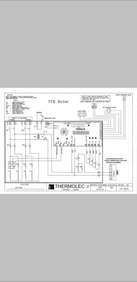
I fired up a new Thermolec B-9TMB boiler this week
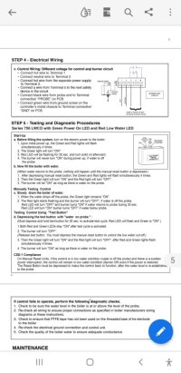
Unsure about wether the thermostat is wired correctly or not. It is an open System and I have the aqua Stat set at 2. Garage temp is at 74 showing at the thermostat. Was worried that the boiler is continuously running. Have not been able to find a legend on the led's on the controller D22-B THF 1503. I have the green pump light on solid, STG 3 light not on, Ld2 light not on, Ld2 flashing red and last led is Mon and it is not on.
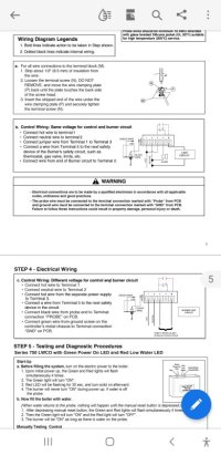
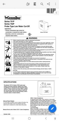
Low water cutoff:
Red to R on thermostat
Black wire to W on thermostat

Thermolec to thermostat:
W1 to w on the thermostat
C to R on the thermostat

Thermostat running batteries so no separate 24v required.
Floor is nice and warm and pretty sure all the air is out of the system. 14 x 20 garage running 1 loop. Boiler is 9kw newly built house with no draft spots

.
20151123_200058.jpg


20151123_200209.jpg
 

Dana

In the trades
Messages
7,889
Reaction score
509
Points
113
Location
01609
Does the boiler & circulator stop when you turn the thermostat down/off?

Heating a garage to 74F is definitely going to make for a high electric bill. What is the thermostat set to?
 

06Nightrain

New Member
Messages
3
Reaction score
0
Points
1
Location
Winnipeg, Manitoba
Figured out the problem, it was a combination of Honeywell mismarking their thermostat base and low water switch was wired to the thermostat causing a jumper. It was running continuous but only on 2 of the 6 heating elements because of this.
 

Janthony

New Member
Messages
3
Reaction score
0
Points
1
Location
98116
Trying to figure out where to wire a 120v low water cutoff to this boiler. Do u have any idea?
 

Fitter30

Well-Known Member
Messages
4,347
Reaction score
795
Points
113
Location
Peace valley missouri
Went on the Thermolec website and it's terrible could find a wiring diagram or on your control what the dial means. Have never seen a control that would need fully insulated screw driver to make a adjustment. Low water control kill the 24vac. What's that white control on the wall?
 
Last edited:

Janthony

New Member
Messages
3
Reaction score
0
Points
1
Location
98116
Went on the Thermolec website and it's terrible could find a wiring diagram or on your control what the dial means. Have never seen a control that would need fully insulated screw driver to make a adjustment. Low water control kill the 24vac. What's that white control on the wall?
 

Janthony

New Member
Messages
3
Reaction score
0
Points
1
Location
98116
Yes website sucks no information really. I did contact the company and happened to speak to the owner. He sent over a wire diagram for 120v low water cut off still trying to figure this out. I'm a master plumber and have plumbed many boilers but never had to do any wiring. For the most part the wiring was very simple. Just this low water cut off is throwing me off. I will attach the wiring diagram and 120v low water cut off diagram that I'm using any help would be appreciated. The boiler model is b11 tmb Termolec Note the lwc shows to different wiring diagrams on for same voltage one for different voltage. Also the boiler is a TMB and not an FFB that is shown in diagram. The owner of the Thermolec company told me it doesn't matter and that it's the same process
 

Attachments

  • lwco.pdf
    67.8 KB · Views: 65
  • Screenshot_20221112-094518_Adobe Acrobat.jpg
    Screenshot_20221112-094518_Adobe Acrobat.jpg
    71.5 KB · Views: 125
  • Screenshot_20221112-094449_Adobe Acrobat.jpg
    Screenshot_20221112-094449_Adobe Acrobat.jpg
    82.4 KB · Views: 100
  • Screenshot_20221112-094437_Adobe Acrobat.jpg
    Screenshot_20221112-094437_Adobe Acrobat.jpg
    72.4 KB · Views: 138
  • Screenshot_20221112-093857_Adobe Acrobat.jpg
    Screenshot_20221112-093857_Adobe Acrobat.jpg
    34.4 KB · Views: 274

Fitter30

Well-Known Member
Messages
4,347
Reaction score
795
Points
113
Location
Peace valley missouri
Is there a diagram in the cover of the control or paper work in the box it came in just for a double check
The diagram in the second picture doesnt make any sense . Power would would put 240vac across limit
Should be a dry contact in the lw control
Low water control can't make out the numbers on terminal strip. Number them 1 - 5 left to right
1 hot
2 neutral
3 common of relay
4 n.c.
5 n.o.
FFB boiler wiring diagram
If you follow the contacts from low water to circuit board and have the contacts can wire 3 - 4
Power control from either picking up power going to the circulator pump before the pump L and N
 
Top
Hey, wait a minute.

This is awkward, but...

It looks like you're using an ad blocker. We get it, but (1) terrylove.com can't live without ads, and (2) ad blockers can cause issues with videos and comments. If you'd like to support the site, please allow ads.

If any particular ad is your REASON for blocking ads, please let us know. We might be able to do something about it. Thanks.
I've Disabled AdBlock    No Thanks