Jim Goodman
JEG in Raleigh
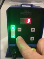
View attachment 63572 View attachment 63572 OK, here's the story: My water is supplied by a well. I have a water softener and 2 backwash filters on the system to treat the water. I did all the installation, so I'm knowledgeable about the system. Those filters and softeners do a good job of treating the water, but we also have sulfur smell problem with our water. To remedy that problem, I bought a hydrogen peroxide injection system to inject a metered amount of H2O2 into the water flow after the pressure tank. This oxidizes the sulfur and removes the smell. There is a 15 gallon tank that I will with a diluted hydrogen peroxide solution. There is a small diaphragm dosing pump that is attached to the top of the peroxide tank and it has a tube coming out of it that is connected to the house water piping and injects the peroxide solution into the water flow. The pump runs on 120 voltage. Then, I have a flow meter installed after the pressure tank and before the backwash filters. This flow meter has a reed switch that is part of it that sends very low voltage signals to the dosing pump when water is flowing through the flow meter....for example, when you turn on a faucet in the house. The dosing pump has a connector plugged into it that receives this signal, and there are electronics inside the pump that are supposed to trigger the pump to stroke 3 times per gallon of water flowing through the flow meter. This makes the pump a proportional pump that increases the number of strokes per minute depending on the volume of water flowing through the flow meter. So, for example, if you have one sink faucet on, it will pump 3 strokes every 15 seconds or so. But, if you have a couple of sinks running and the shower running, then it should pump 3 strokes maybe every 5 seconds, etc. The number of strokes that the dosing pump pumps per gallon of water was programmed by me, following the directions of the manufacturer, and the number of strokes can be programmed up or down.
My problem is that the pump loses the program and does not pump proportionally. Once you turn on the water....even just a bathroom sink faucet....or flush the toilet, the pump takes off and starts pumping non-stop, regardless of the volume of water running through the flow meter. So, I'm burning through 15 gallons of my peroxide solution every couple of weeks, where it should be lasting me a couple of months, based on our typical water usage. Now...the dosing pump also has a manual setting, and when you put it in the manual setting, you can set it so that it pumps 3 strokes, every 15 seconds, or some other time interval of your choosing. The only thing is, that when the pump is plugged into the wall receptacle, and you have set it in manual mode, it starts pumping that 3 strokes every 15 seconds, for as long as it is powered on, regardless of whether you are using water or not....it just starts pumping to that interval, and keeps pumping.
OK, that's the background. Now, one other thing....the pump is designed to be turned on and off repeatedly, without damaging the pump. So what I want to do is have the pump power up, in manual mode, only when water is flowing through the flow meter, and then power off when water is no longer flowing. I'll lose the proportional feature, where the pump strokes increase in frequency when more water if flowing through the flow meter, but that's a compromise I can live with. To implement this new strategy, I want to use a relay to turn on power to the pump (and the pump would be in manual mode) and have that relay activated by the reed switch that is in the flow meter.
This is where I need help from the forum members. I can do basic house wiring....receptacles, switches, run new circuits to the panel, etc., but I have no idea what kind of relay I need to use or how to hook it up to the power going to the dosing pump. The pump is plugged into a conventional GFCI receptacle.
QUESTION 1: Do I make up some kind of j-box that contains the relay and has a cord coming out of it with a male plug end on it to plug into the GFCI receptacle, and then have another short cord with a female cord end on it to receive the male plug from the pump so the pump is actuated by the relay?
QUESTION 2: When I was trying to troubleshoot the original problem, I took a volt meter and put it on the wires coming from the reed switch and it registered 0.001 volts when the switch fired. So I'm guessing the relay would need to have enough sensitivity to be triggered by that voltage, is that correct.
QUESTION 3: Any advice on the relay to use and how to wire it up would be greatly appreciated. If what I suggested as a setup in QUESTION 1 is a good idea, please let me know. If it's a bone-headed idea, please also let me know. I don't even know what the relay would look like, or how big it would be, so I'm clueless on how to set this up.
I've reprogrammed the pump dozens of times, and it works as it should for 20 minutes and then loses the program. I give up. It's too late to return it and it was $300-$400. I want to try this idea. Any help would be most appreciated. Thanks!