Need critique on residential plumbing layout

Users who are viewing this thread

Jeff H Young

In the Trades
Messages
8,893
Reaction score
2,221
Points
113
Location
92346
Do you have a gauge that has a secondary needle that records the highest pressure? If so don't trust . closing a valve in the house quickly or a ballcock on toilet, or even irrigation valve could cause a water hammer which can spike the needle. At least I never trust them.
City doesn't always know how much pressure you have at all times, could be a fluke if you just put the gauge on and went to bed next day saw a recorded needle at 100 it may not be accurate.
 

Mikha'el

Member
Messages
76
Reaction score
11
Points
8
Location
Texas
The overall project is also big... I'm rebuilding about 50% of the house, and doing about half the work myself, including things like design and install of the radiant heat system, electrical, etc. A bit too much with a 55hr a week job and family, but have to keep shoveling! Multi-year construction living, not much sleep.
Are you living in it while you remodel/rebuild? Been there, doing that. Everything takes 5x as long... "would've been easier to knock it down and start over" often comes to mind. o_O
 

Rossn

Member
Messages
365
Reaction score
17
Points
18
Location
Denver, CO
Totally agreed, Jeff. - in fact the gauge I was using has that secondary needle that bounces around easily. I feel like I was seeing the pressure real-time, previously, but it has now been a few years and I can't fully recall. I'm putting a permanent pressure gauge in the mechanical room that I can glance at regularly and will hold on any PRV until I see a real issue.

Mikha'el - yeah, unfortunately... have to learn the hard way that it would have been smarter that way!! The money pit becomes reality.
 

Mikha'el

Member
Messages
76
Reaction score
11
Points
8
Location
Texas
Mikha'el - yeah, unfortunately... have to learn the hard way that it would have been smarter that way!! The money pit becomes reality.
Yup... we're nearly 7 years into what was going to be a "refresh"... then you live in it awhile and get ideas, plans change, etc.
Now after basically gutting the place and adding 600+ sqft I'm in serious git-r-done mode so we can sell up.

Maybe build a treehouse (of sorts) out in the country. :)
 

James Henry

In the Trades
Messages
1,578
Reaction score
403
Points
83
Location
Billings, Montana.
I've posted a couple scanned pages for your listening pleasure. the scan job didn't turn out to well but they work. Start reading on the paragraph that starts with the word, "Analyze", you can use this to calculate your water flow and FPS coming out of the pipe at the entrance to your house to get an idea of what you have to work with. Hope this helps.
 

Attachments

  • PAGE 1.jpg
    PAGE 1.jpg
    90.2 KB · Views: 137
  • PAGE 2.jpg
    PAGE 2.jpg
    61.2 KB · Views: 140
Last edited:

Rossn

Member
Messages
365
Reaction score
17
Points
18
Location
Denver, CO
Thanks for taking the time to share that out, James! That all makes sense.

I took a bunch of flow and pressure readings today using fixtures and irrigation, and also did more poking around the meter.

The good news is that there is actually 1" copper feeding the meter, of course going by the code table, going to a 1" meter doesn't help me much until I upsize to at least 1-1/4" for the service line. It does look like where my 1" copper leaves the meter pit (90 degree bend), the tubing is not bent uniformly, and so you have to wonder how the rest of the install went.

The bad news is that it seems like I'm going to be limited to 8-9 GPM to keep pressures above 40psi. The furthest fixture is about 14' above the irrigation manifold... I think I recall that means -7psi. Does effective length of a branch affect pressure, or only flow rate?

Ultimately, I'll have to upgrade the service into the house, but practically, can probably get by for a while.

I'll have to run the numbers on the rest of the branches in the house, tomorrow evening.

flow_vs_pressure_data_202104.jpg
 

wwhitney

In the Trades
Messages
6,557
Reaction score
1,841
Points
113
Location
Berkeley, CA
OK, trying to read the numbers off your graph, I get (? means the number is off pattern):

Location / Distance / PSI at (0 GPM, 7.2 GPM, 8.4 GPM, 10.2 GPM) / Delta PSI
Yard Hydrant / 114' / (64, 57, 52 ? , 50) / (7, 12 ?, 14)
Irrigation Manifold/ 268' / (61, 50, 46, 39) / (11, 15, 22)

So the section from the yard hydrant to the irrigation manifold (154') is causing pressure drops of (4, 3?, 8) psi for flows of (7.2, 8.4, 10.2) GPM. The first and last agree with the Hazen Williams (empirical) formula, which says the pressure drop should vary as the flow Q raised to the 1.85 power. (10.2/7.2)^1.85 = 1.9 or approximately 2.

This calculator says the theoretical drop for 10.2 GPM through 154' of 0.995" ID plastic is 5 psi, and I thought the roughness coefficient for copper was the same as plastic. Since you are seeing 8 psi, either I'm wrong about the roughness coefficient, or the effect is due to some small constrictions.

Using the Yard Hydrant - Irrigation Manifold behavior as a benchmark, the Water Main - Yard Hydrant pressure drop is about 175% as much. So that either means (a) the distance from the Water Main to the Yard Hydrant really is around 270' (meaning from the water main to the meter is around 150') (b) the effective length of the meter is much higher than I expect (it shouldn't be causing that much pressure drop at these flow rates) or (c) there is a much bigger obstruction/kink in the Water Main - Yard Hydrant segment than there is in the Yard Hydrant - Irrigation Manifold segment. [For (c), you can directly do something about it if it's after the meter; it could be before the meter, which a pressure/flow test at the meter would show, not sure if your utility would do something like that.]

When you say the meter is supplied by 1" from the utility, that doesn't actually mean it's a 1" meter. The meter should have a model number on it, or a size marking. Your water bill might also say what their billing system thinks your meter size is. And if you measure the lay length (distance between union connections) you can infer something about the meter size, those are standardized.

Cheers, Wayne
 

Reach4

Well-Known Member
Messages
38,858
Reaction score
4,429
Points
113
Location
IL
The bad news is that it seems like I'm going to be limited to 8-9 GPM to keep pressures above 40psi. The furthest fixture is about 14' above the irrigation manifold... I think I recall that means -7psi. Does effective length of a branch affect pressure, or only flow rate?
Interesting.

When you take the readings, are you drawing water from the particular spigot? I think readings, such as taking readings at the hose bib or the irrigation manifold, while only drawing 5 gpm, or whatever it can do, from the tub spigot would be interesting and useful to see where the drops occur on the way to the tub.
 

Rossn

Member
Messages
365
Reaction score
17
Points
18
Location
Denver, CO
Thanks for the engineering check and thoughts on this Wayne!! Some notes and data, below.

Reach, the sources of water running are a across a number of diverse sources, combined. More information than probably desired, but listed those below for the idea. I could get 5GPM pressure for the laundry sink at the irrigation manifold and yard hydrant, as well.

Know that the main distribution line in the home is 3/4" (why I thought going to 1" was going to be sufficient) - so I included in my test some combined runs with some (normally 10.2 GPM) irrigation running outside, and the fixtures running inside. Also, 2 outside zones running concurrently (that didn't irrigate very well!). In most instances, I took pressure readings at at least 2 locations (hose bib that feeds off the interior, irrigation manifold before the supply enters the home, and at the yard hydrant). You all probably gathered already, but the volumes are not coming from the same location the pressure was taken, and the front hose bib, feeds from the inside of the house.

I have 2 additional readings for the yard hydrant, alone -- which I didn't include in the below chart, but are relevant.
Yard Hydrant - 19.8 GPM. Pressure at house hose bib: 5 psi. Pressure at Irrigation manifold: 16 psi.

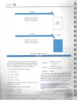
The distances... Yard Hydrant to Meter pit should be pretty good (though does not account for the 6' rise to the outlet of the yard hydrant), and the edge of the residential street to the meter pit is about 17', with the lines entering the pit about 4.5' underground (I am guessing the main may be deeper). Yard hydrant to irrigation was measured in the air, but could vary some, as I don't t know the exact path, and (more importantly, it dives under a 7' deep, 15' wide ditch, so I made some assumptions there... definitely not exact).

Yes, it is a 3/4" meter, but the utility said it would have a 3/4" line coming into it, so that means if upgrade is every necessary, cost should be much lower. It is a relatively new meter, and if needed I can get the model number.

I'll see if I can chart out the flow versus pressure drop, though again - numbers are probably +/- 1.5 psi, based on the duration of the test (though in most instances I didn't see variance). Yes, I was wondering about the diverging nature of the green and other lines. Very, very interesting comments on the first section possibly being the constriction. I wonder if that bend leaving the meter pit, where it looks like the pipe went more oval is the culprit.

I would say that my methodology had some room for error (esp, given the below), and I had an outlier or two that I scratched my head on, then omitted from the plot (red triangles, below). Here are a few potential sources of inaccuracy:
  • Biggest error is likely around the reading of flow at the meter. I took 10s readings, and those .xx digital numbers are moving real fast at 10+gpm... higher flows could easily have varied 0.5-1GPM.
  • These tests too quite some time to test, and during that time, there was a little variance in static pressure... I think +/- 1.5 psi. Having only one gauge, the pressures were taken in groupings at a given pressure point, not running around the yard for each one.
  • At the start of the test, the pressure would drop low, then come back up (e.g. drops from 60 -> 35, then stabilizes at 42)
  • I always had to let the test run for maybe 30 seconds, then relieve some pressure from the gauge via schrader valve, or it would read too high (still digesting that).
  • Now that we have the big picture, if a more accurate/precise test needs to be re-run, I could do that.
All this said, ultimately I'll be plumbing the inside, and having to come back in resolve this after the remodel, but it is good get an idea now of what may be going on (which is largely, probably the undersized supply pipe).

upload_2021-4-9_10-48-3.png
 

Rossn

Member
Messages
365
Reaction score
17
Points
18
Location
Denver, CO
Ok, could use a little guidance here as I try to work the numbers on this plumbing design!

In the moment, I'm struggling with the proper (IPC 2015/2018) way to go from WSFU's to GPM or Tubing size. To complicate things, I will have one end of my system using PEX, the rest copper

3 ways it seems to e done:
  • MethodA: I watched some tutorials that showed use of a Copper Size, Pressure Drop & Velocity vs Fixture units chart, and
  • MethodB: went through the example in IPC 2015/2018 E103.3, which uses table E103.3(3) 'Table for Estimating Demand' (no apparent velocity or specific tubing consideration)
  • MethodC: also used Table E201.1. (not sure I'm using this correctly)
Each approach gives a different result!

Type L Copper, Cold Water, for max Fixture Units:
Size GPM @8ft/s | MethodA | MethodB | MethodC
1/2" 5.1 | 6.9 | 2 | 2.5-3
3/4" 10.5 | 15| 15 | 32
1" 18 | 30-33 | 15 | 32
1-1/4" 26.6 | 52 | ? | ?

Which is the right way to go about this?

Based on Terry's page and some of these charts, it almost seems that the interpretation of a WSFU has changed across various codes or time. Is that possible?
 
Last edited:

Rossn

Member
Messages
365
Reaction score
17
Points
18
Location
Denver, CO
I think I've answered the question about is a WSFU always a WSFU, and it is not. Below seems to show that the interpretation of a WSFU differs significantly between IPC and UPC, and may explain why use of some of the charts (not included in the IPC) yield different results... perhaps it was based on UPC vs IPC?

Would still love to hear the proper way to go about WSFU to GPM in IPC. Sounds like it using one of the two built-in tables, though not clear which one is better.

IPC 2018:
upload_2021-4-15_23-49-42.png


UPC 2018:
upload_2021-4-15_23-51-34.png
 

Attachments

  • upload_2021-4-15_23-48-37.png
    upload_2021-4-15_23-48-37.png
    97 KB · Views: 107

Jeff H Young

In the Trades
Messages
8,893
Reaction score
2,221
Points
113
Location
92346
Just wondering why you don't size your water system according to fixture units, meter size , length of run etc.? I never used pressure gauges all over and GPM flow and all that . it was a calculation . we calculate this before a house is even plumbed you just need to know static pressure the pressure is the same 500 foot away as it is a meter. but you do need a number. its pretty simple not an exact science . if you run everything bare minimum . if something is 199 foot and 200 calls for a bigger pipe for god sakes go with next size, or take your chances it will probably be ok , but that means higher velocity more wear on pipe. A little undersize wont kill you but why do it wrong? And going oversize has only slight benefit and some drawbacks.
By such long run I'd have no 1/2 inch in the house other than stubouts and maybe the last few feet like on commercial where we have 3/4 x1/2 90s at sink stub outs or w/c
 

Rossn

Member
Messages
365
Reaction score
17
Points
18
Location
Denver, CO
Hi Jeff - that is definitely the intent. This thread did start down the rabbit hole, as we discovered there is actually a service pipe sizing issue (which is where all the pressures came in), but right now, need to focus on sizing the home properly. I will have to come back to that separately.

I am trying to make sure that I do not cause any practical issues, and also remain code compliant. There are some unique situations here, such as some fixtures > 100'.

I do not currently understand the proper way to go from Fixture Units to GPM or pipe size (I will have one end in Pex), using the IPC fixture units, as the two ways I have seen in 2015 IPC seem to give conflicting values. It seems using table E103.3(3) 'Table for Estimating Demand' is the proper way to get to GPM, then size based on 5ft/s or 8 ft/s, but there must a different way this is typically done.

Edit: Yes, only intending to use 1/2" for the stub outs. However, I think there will be both 3/4" and 1" in other sections of the home.
 

Rossn

Member
Messages
365
Reaction score
17
Points
18
Location
Denver, CO
Hello everyone - I want to start off by thanking this awesome forum community of persons who are so generous with your time; you all have been very educational, supportive, and patient, as I have been going through this project that is a bit over my head, and I a so very appreciative of that!!

I spent about 30 hours since my last post getting to a revised design - lots of research and learning along the way. I'm attaching a PDF of the full revised design, and would be so grateful for any review and feedback on any part of it!

I ended up with a mix of mostly Pex-A on the hot water side due to delivery times (home runs) and flexibility, and Copper (L) on the cold water side (prefer that for drinking and also sizing played well). P stands for Pex, C stands for Copper. WSFU's shown, per IPC (2015). Note, on average, I will have 4-5 people living here.

Taking off next week to plumb kitchen & west, and ordering parts today!

I have a dozen questions, but will just ask 3 at a time and be as succinct as possible:
  • For my main distribution Line, I come back at 26.4 GPM (40.3 WSFUs). With these revised numbers, can you confirm I am OK with 1-1/4" (seems on the cusp, but also to be what you all suggested previously)? I hope so, as my press tool only goes up to 1-1/4, and some devices, such the Flo only come up to that size.
  • DHW - you can see I have a mixing valve off the indirect water heater, which is fired by a 230K BTU boiler (smaller when replaced in 10 years). WSFU calculations suggest I am at limits with 1" on the supply, and that I need 1-1/4" through the Mixing valve and 2nd tee. Practically speaking, is 1" OK, or do I need to go to 1-1/4"?
  • 2 lavs downstairs, 10' west of the hot water heater. One will be used regularly, the other, not very often. Am I better from a user experience + safety perspective doing (2) 3/8" Pex-A home runs or 1/2" Pex-A branched? If running on 1/2" Pex-A, is it too much to add a laundry sink/tray to that?

THANKS!!!
 

Attachments

  • APLU_Plumbing_layout_3D-v2.1.PDF
    84.6 KB · Views: 178
Top
Hey, wait a minute.

This is awkward, but...

It looks like you're using an ad blocker. We get it, but (1) terrylove.com can't live without ads, and (2) ad blockers can cause issues with videos and comments. If you'd like to support the site, please allow ads.

If any particular ad is your REASON for blocking ads, please let us know. We might be able to do something about it. Thanks.
I've Disabled AdBlock    No Thanks