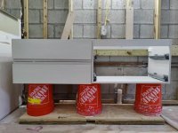
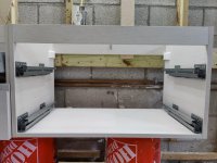
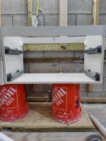
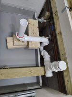
Yes. Its a floating vanity so it is secured to this double 2 x 6.wwhitney said:Is that for supporting the countertop or what? If it's for the countertop, it would be fine to interrupt it for your plumbing
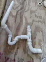
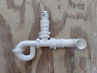
I can potentially cut just into the bottom portion of the 2x6. How much bigger do I need to cut out the wall box? An inch from each side of the AAV?wwhitney said:So it'd be like post #2, either with the san-tee as you have or as I originally proposed, with a wall box cut into the ledger and possibly that top rail of the vanity.
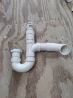
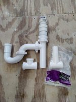
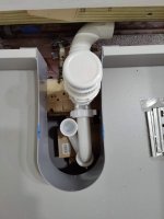
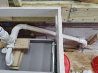
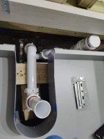
Yes, only that in this option, I need to leave a wall cavity for the p-trap and AAV since they would not fit behind the drawer and drywall.wwhitney said:BTW, are you going to be install sheetrock between the furring and the vanity? That would be typical.
https://terrylove.com/forums/index.php?threads/master-bath-renovation.95140/page-3#post-693879
Thanks for all the help. I have a few options to think about and chose from.
")