HTP UFT-80W Boiler Piping

Users who are viewing this thread

LST3

New Member
Messages
3
Reaction score
0
Points
1
Location
14464
Hey guys, I am going to apologize in advance for the long post, but I know people hate when threads don't include enough information. Feel free to skip to the bold part for my actual question.

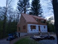
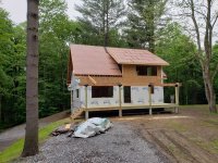
I am currently building a cabin in NY near the Adirondacks. We are utilizing in-floor radiant to heat the building (with provisions for adding a low temp fin tube loop to the 2nd floor loft if needed.) The building will have a wood stove in it for supplemental heat, but I don't want to factor that into the design and be forced to use it.

I have been researching everything and seem to have narrowed down my design to use an HTP UFT-80W boiler and a SSP-40 indirect HW tank for DHW.

I am unsure whether I should pipe the boiler direct, or with P/S piping.The boiler manual shows it being piped in either fashion, but I am not sure that my flowrates support this (or that it would be the best way to go considering we may add fintube in the future.)

In the basement slab, we have 4 loops of 1/2" pex (250', 250', 230' and 230') laid on top of ~2 1/2" Creatherm insulation panels (R10 according to spec sheet). LoopCAD seems to calculate an output of 13,400 BTU/Hr @ 100° supply temp and 1.5 GPM (for a 20° delta.)

We will be installing the radiant tubing in the 1st floor joist bays in a few weeks using heat transfer plates and R19 fiberglass insulation below (pushed loosely up against the plates.) I have designed the tubing layout with 8 loops, approximately 195-205' each. For a total output of 23,900 BTU/Hr @ 158° supply temp and 2 GPM (for a 20° delta.) I know that the supply temp is not ideal in this scenario, but the heating load is pretty big for this floor and I haven't figured out a better way to lower it (we can't justify the extruded aluminum plates, and the floor/walls have already been built, so we don't want to install tubing above the floor.) I am hoping that outdoor reset will still keep us condensing the vast majority of the time.


Does it seem like the best route to pipe the boiler directly, with one circulator for each zone? I would install a flow meter on each zone to verify adequate flow through the HX at all times (the manifolds have those flow meters for each circuit, but I don't know if I want to trust those.) The manual lists a minimum flow rate of 1.3 GPM at minimum output. We are slightly above that, so in theory it seems as though everything should work fine with direct piping, and it would save on having an additional boiler loop pump running all the time. But I keep going back to thinking that I should just stick with a tried and true P/S setup.

Also, if I were to go with a P/S design, has anybody used a variable speed circulator for the primary loop with this boiler? I see that the boiler has a 0-10v output, but the manual doesn't mention anything about using that to drive a circulator pump. And I am not sure if it would be a good idea to use a variable speed circulator driven by a delta T. Just seems like a waste to have the boiler pump circulating away at 3-5 GPM or whatever even when the secondary loop is only flowing at 1.5 GPM (say if only the basement loop is calling for heat.) In my mind, this equates to high return water temps, which could keep the boiler from condensing adequately like we want. I have also heard that it is not a good idea to have the primary loop running at a higher GPM then the secondary loop, but I don't see any way around this besides using a variable speed circulator.

In either case, I would use the boiler controls to vary the 1st floor loop between minimum/maximum temp (based on outdoor reset) and just use a mixing valve to supply the 100 degree water to the basement loop (I have considered using one of those Taco mixing valves with built in outdoor reset, but I am finding it hard to justify bothering with that since the supply temps are so low on this loop even at design conditions anyways.)


Building Info
The building is 1000 S.F. per level (levels include a below grade basement, a first floor, and then a partial 600 S.F. second floor). Insulation will be 2" of closed cell spray foam with fiberglass batts over top to meet the R21 code requirement, and 3-4" of closed cell spray foam on the roof with fiberglass batts to get us to R49 for the roof. Zoning will be pretty simple, one zone for the basement slab and one zone for the 1st floor, controlled by thermostats mounted on the wall (or potentially a floor sensor of some sort if needed.) We will be installing pex in the walls (and adding an extra "zone" connection to the boiler piping) to utilize at a later time for low temp baseboard heat if we decide that the 2nd floor is not adequately heated (we would like to avoid this, but don't want to shoot ourselves in the foot if it turns out the building doesn't heat like we planned.)

Building heat loss is as follows (calculated using Trane Trace 700, -8° DD),
Basement - 14,500 BTU/Hr
1st Floor - 20300 BTU/Hr
2nd Floor - 9,400 BTU/Hr


Thank you in advance for any insight or advice that is given. I am open to any suggestions for the design. The basement loop is the only thing "set in stone" at this point, but the 1st floor loop will be installed in a few weeks. Nothing else from the heating system has been purchased yet.
 

Dana

In the trades
Messages
7,889
Reaction score
509
Points
113
Location
01609
In general the pump for every zone approach results in crazy-overpumping and excessive electricity use. A single "smart" ECM drive pump and zone valve approach usually works better on both upfront cost and efficient use of electricity.

The total heat load seems high for a 2000' house over an insulated 1000' conditioned basement. The fact that the top floor's load is ~1/3 less than the basement's is an indication that the basement isn't adequately insulated, or it's a walk-out with a huge amount of glazing (?).

Without knowing where you are in the process it's hard to suggest the cheapest/best way to deal with the insulation, but what's been described is problematic, and not up to current code minimums for your actual climate zone.

Closed cell foam between wall framing is a waste, and it's one of the least-green ways to insulate a house. Air sealing the framing to the sheathing 360 degrees around the interior of each stud bay and R23 rock wool with 2-mil nylon (Certainteed MemBrain) detailed as an air barrier behind the wallboard has comparable performance at a much lower price point, and has more drying capacity for the sheathing. Even a full 5.5" of open cell foam and 2-mil nylon (no need to detail for air tightness with a o.c. foam fill) would be better bang/buck, and more resilient to exterior moisture drives.

Also, R21 does not meet IRC 2018 code minimum for US climate zone 6 (which is all counties in the Adirondack region). See TABLE N1102.1.2. It needs at least some exterior insulation to get there, even if going for compliance on a U-factor basis. Even a full cavity fill of closed cell foam wouldn't get you to under the required U0.045 (= R22.2 "whole wall R") spelled out in Table N1102.1.4. If the siding isn't up yet it's possible to put 2" of foil-faced polyisoon the exterior, and cheap R20s in the 2x6 bays for a highly resilient and code compliant wall. But if that ship has sailed, describe how far along you are.

An unvented R49 roof combining closed cell foam and batts in US climate zone 6 requires a minimum of R25 at the roof deck, and no more than R24 out of the batts to have adequate dew point control at the foam/fiber boundary. Anything less than R25 would violate the IRC 2018 prescriptives. It really needs to be at least 50% foam independent of the total R, but more is better. Using an HFO blown 2lb foam you can get R27-R28 out of 4" of foam, add R23 rock wool for ~R50 total, 54% of which is foam for dew point control, and you're all set. But doing it with 3" of foam + R30 rock wool would come with some risk of wintertime moisture accumulation/frost in the fiber and potential mold issues in the spring season. Using cheapr climate-damaging HFC blown foam you'd be pushing your luck even at 4", but you could get there with 5". But HFC blown foam needs to be installed in lifts of no more than 2" at a pass with a curing period between- violating that is both a quality issue and potential fire hazard as it cures. (Most HFO blown foams can handle 5" or more in one pass.)

A cheaper/better way to go would be to put 5" of rigid roofing polyiso board above the roof deck (a minimum of 2 layers, overlapping the seams by a foot or more) held in place with a 5/8" nailer deck through screwed to the structural roof deck with pancake head timber screws. If using reclaimed roofing foam the cost of the foam is cheaper than the R23 rock wool batts on the underside of the roof deck(?). With used roofing polyiso foam, derate the labeled R5.7 to a more realisitic R5/inch (it's performance at temperatures that matter) when calculating it for dew point control at the roof deck, so it would take 5" to get adequate dew point control on 5.5" /R23 rock wool batt.
 

LST3

New Member
Messages
3
Reaction score
0
Points
1
Location
14464
In general the pump for every zone approach results in crazy-overpumping and excessive electricity use. A single "smart" ECM drive pump and zone valve approach usually works better on both upfront cost and efficient use of electricity.

The total heat load seems high for a 2000' house over an insulated 1000' conditioned basement. The fact that the top floor's load is ~1/3 less than the basement's is an indication that the basement isn't adequately insulated, or it's a walk-out with a huge amount of glazing (?).

Without knowing where you are in the process it's hard to suggest the cheapest/best way to deal with the insulation, but what's been described is problematic, and not up to current code minimums for your actual climate zone.

Closed cell foam between wall framing is a waste, and it's one of the least-green ways to insulate a house. Air sealing the framing to the sheathing 360 degrees around the interior of each stud bay and R23 rock wool with 2-mil nylon (Certainteed MemBrain) detailed as an air barrier behind the wallboard has comparable performance at a much lower price point, and has more drying capacity for the sheathing. Even a full 5.5" of open cell foam and 2-mil nylon (no need to detail for air tightness with a o.c. foam fill) would be better bang/buck, and more resilient to exterior moisture drives.

Also, R21 does not meet IRC 2018 code minimum for US climate zone 6 (which is all counties in the Adirondack region). See TABLE N1102.1.2. It needs at least some exterior insulation to get there, even if going for compliance on a U-factor basis. Even a full cavity fill of closed cell foam wouldn't get you to under the required U0.045 (= R22.2 "whole wall R") spelled out in Table N1102.1.4. If the siding isn't up yet it's possible to put 2" of foil-faced polyisoon the exterior, and cheap R20s in the 2x6 bays for a highly resilient and code compliant wall. But if that ship has sailed, describe how far along you are.

An unvented R49 roof combining closed cell foam and batts in US climate zone 6 requires a minimum of R25 at the roof deck, and no more than R24 out of the batts to have adequate dew point control at the foam/fiber boundary. Anything less than R25 would violate the IRC 2018 prescriptives. It really needs to be at least 50% foam independent of the total R, but more is better. Using an HFO blown 2lb foam you can get R27-R28 out of 4" of foam, add R23 rock wool for ~R50 total, 54% of which is foam for dew point control, and you're all set. But doing it with 3" of foam + R30 rock wool would come with some risk of wintertime moisture accumulation/frost in the fiber and potential mold issues in the spring season. Using cheapr climate-damaging HFC blown foam you'd be pushing your luck even at 4", but you could get there with 5". But HFC blown foam needs to be installed in lifts of no more than 2" at a pass with a curing period between- violating that is both a quality issue and potential fire hazard as it cures. (Most HFO blown foams can handle 5" or more in one pass.)

A cheaper/better way to go would be to put 5" of rigid roofing polyiso board above the roof deck (a minimum of 2 layers, overlapping the seams by a foot or more) held in place with a 5/8" nailer deck through screwed to the structural roof deck with pancake head timber screws. If using reclaimed roofing foam the cost of the foam is cheaper than the R23 rock wool batts on the underside of the roof deck(?). With used roofing polyiso foam, derate the labeled R5.7 to a more realisitic R5/inch (it's performance at temperatures that matter) when calculating it for dew point control at the roof deck, so it would take 5" to get adequate dew point control on 5.5" /R23 rock wool batt.


The zone pumps vs zone valves was more a personal preference after going back and forth with it. With my piping plan, there would only be a difference of one additional pump when going between the two (one zone pump, one boiler pump, and one DHW pump VS the 4 pumps that I was planning to use.) I was under the impression that it would be close to or more efficient to use smaller individual circulator pumps instead of a single larger pump because when only one zone is calling for heat, only the small pump would be running (VS having the larger pump running with any zone call.) I guess that train of thought probably stems from older pumps though, before variable speed pumps have come so far. I am open to advice if you think the zone valves would be a better way to go.

We are actually located in climate zone 5, hence the insulation plan. We are still in the NE part of Oswego County there, which is about as far North as zone 5 goes.

The heating load is high because of all of the windows that are on the building. The "1st floor" (left side of the building in the picture, with the steeper roof) is a vaulted ceiling for half of it, and one end has a ton of windows in it that go almost up to roof level. The 2nd floor has relatively short walls due to the sloped roof, but the large windows play a role in that level as well (there is a matching large window in the back wall, and two smaller windows on the end wall for this floor.) I have attached two pictures that I had handy to give you an idea of the building layout, a picture is worth a thousand words here rather then me trying to describe it to you (note that the tyvek on the left end wall hasn't been cut and folded at the window openings yet, so it looks like there are no windows on the upper part of that wall in that picture.) Note that the floor for the second floor is only going to be wood planks, no drywall ceiling or any sort if airtight flooring. It is more just a loft area IMO, with a finished wall on the end to close it in from the other half of the building.

The basement is a 10" thick poured concrete wall with a walk out door on one end, and it will be finished with 2" of foam board (nothing has been finished in the basement yet, so this could be subject to change, but the basement heating load did not seem abnormally high to me, especially since I don't see any problem covering that heating load with the available radiant slab output.)

I am pretty confident in my heat load calculations, I have actually verified them using a few different methods and always end up within about 10-15% of the same result. In a perfect world, it will end up being lower then I have calculated, but according to the math, those are the number that it works out to.


We have gone back and forth with the insulation method. We want the closed cell foam for its air sealing benefits (especially since this building will have no drywall, or any other sort of interior air/vapor barrier), but the price gets out of hand quickly when using it alone (and there is minimal benefit from it beyond a certain point due to the framing losses as you mentioned.) We ended up going with the minimum thickness we could safely use (while avoiding moisture issues) and filling the rest of the cavity with fiberglass batts.

The siding has not been installed yet, but the windows have been installed, which would make it difficult to add foam board on the outside at this point. It would also make it difficult to firmly attach the clap board siding to prevent it from curling. The siding is going to be 1" rough cut Larch lumber. Note that the interior will be finished with tongue and groove pine board as well, with no interior vapor barrier between the closed cell foam and the inside space.
 

Attachments

  • 20190518_203356.jpg
    20190518_203356.jpg
    148 KB · Views: 203
  • 20190616_175806.jpg
    20190616_175806.jpg
    172.5 KB · Views: 209

LST3

New Member
Messages
3
Reaction score
0
Points
1
Location
14464
I also should have noted that the system will be filled with a 40% glycol solution. Being that it is a camp and not a primary residence, there may come a time when we decide to winterize it for a season instead of leaving it heated (hopefully not, but better to plan for the future.)

Thanks for your insight so far Dana!
 

Dana

In the trades
Messages
7,889
Reaction score
509
Points
113
Location
01609
With an ECM drive smart pump operating in a pressure feedback mode the power drops when different zones turn off- it's the same as having separate super-efficient perfectly sized pumps on each zone. You can set the flow to whatever it needs to be with globe valves or ball valves- when the valve is throttled back, the power use goes down.

Current code-min on basements for climate zone 5 & higher is R15 continuous insulation. At 2" there is no foam board that would meet that.

In zone 5 installing 1.5" of polyiso on the exterior of a 2x6/R20-R23 wall is sufficient dew point control at the sheathing layer to allow using just standard latex paint as the interior side vapor retarder. That would be a better than code, and highly resilient build, since the drying of the sheathing toward the interior can be left fairly vapor-open.


If exterior foam isn't an option, in zone 5 going with rock wool R23s in the framing and using back ventilated cladding (vinyl siding works, as does any other siding if there is at least a 1/4" rainscreen gap between the siding & housewrap) can also use plain old latex paint on the interior as the vapor retarder. See Table R702.7.1. The back ventilated siding approach going to be a cheaper and more moisture-resilient build than a 2" closed cell spray foam flash'n'batt, at a comparable thermal performance level, since the sheathing can dry freely to both the interior and exterior. But even if the low permeance spray foam is already in place, going with back ventilated siding would provide quite a bit of resilience, since the air gap is a powerful capillary break against exterior moisture drives, as well as an excellent drying path to the exterior.

If it's only going to be t&g on the interior (no gypsum board), going with 5.5" of open cell foam would get you the code-min R20 and will air seal as-good or better than 2" of closed cell, while allowing better drying capacity toward the interior, and would cost less than the 2" of closed cell foam (using less polymer too, and only water as the blowing agent, not the industry standard HFC245fa which is an extremely powerful greenhouse gas, ~ 1000x CO2 @ 100 years.) A sheet of 2-mil nylon (MemBrain) under the t & g would be more effective at controlling interior moisture drives than standard latex paint. With an air tight assembly the holes in the vapor retarder for nails or electrical boxes has a negligible effect.

Since the foam only air-seals the rafter bays, be sure to put a bead of polyurethane caulk between the subfloor and bottom plates, as well as between any doubled-up framing such as top plates, jack studs, window headers, etc. Air sealing is the cheapest thermal performance you can buy, and adds quite a bit to the overall moisture resilience by inhibiting air-transported moisture flows.

The rafter spacing seems ultra-tight, which means the thermal bridging will even more severely undercut the performance of spray foam at the roof deck. How deep are the rafters? (2x10s? 2x12?)

With 12" o.c. spacing R49 between the rafters here using 4" of spray foam + R30 batts in a 2x12 rafter bay would not meet code performance on a U-factor basis, even though it still meets code on R-value basis. (Either would be allowed.) In zone 5 the roof deck is protected from wintertime moisture accumulation as long as more than 40% of the total R is rigid foam board above the roof deck. With 4" of 2lb polyiso roofing foam held in place with a 5/8" OSB/plywood nailer through screwed to the structural roof deck you'd have a labeled R22-R23 (R20+ when derated for temperature) above the roof deck, which is enough to accommodate up to R30 of fiber insulation between the rafters. (If the rafters are 2x8, sprayed cellulose would be best due to it's hygric buffering capacity.) It's critical to air seal the roof though, particularly at the ridge, or copious amounts of air could bring enough moisture out to prematurely rot the nailer deck along the exfiltration path. A fully adhered membrane such as Grace Ice & Water Shield or Henry Blueskin RF200 etc directly on the structural roof deck may be "worth it", even though the ZIP is pretty good on it's own if detailed correctly. The nailer deck can get the usual #30 felt underlayment.

For the fastener specs & spacings for an exterior foam approach to the roof, refer to nailbase panel manufacturers' specs.
 

Dana

In the trades
Messages
7,889
Reaction score
509
Points
113
Location
01609
I forgot to mention...

In addition to better drying for the sheathing, a rainscreen approach would also mitigate against the rough sawn large from splitting or curling, since it would dry quickly and evenly in both directions. To establish the gap you can either using 1x4 furring at every stud through-screwed to the studs with 2.5" pancake head timber screws (eg Fastenmaster HeadLok) 24" o.c. and mount the siding on the furring. Alternatively, cutting strips of 3/8" plywood as furring and using longer fasteners for the siding also works. To avoid the air spaces from becoming critter-condos, install ridge-vent mesh and bug screen between the furring at both the top and bottom of each furring bay. That still allows sufficient convection drying, but limits access to insects & rodents.

Insect%20screen%202.jpg


(note- if using milled furring rather than plywood strips, go with 1x4s not 1x3s- the latter tend to split, and are often corkscrewed & bent.)

Purists will also add top venting details at window trim to guarantee air-purging of moisture that gets directed there by the window flashing etc:

3659388ee2dddbbf29aed5f716587497.png
 
Last edited:
Top
Hey, wait a minute.

This is awkward, but...

It looks like you're using an ad blocker. We get it, but (1) terrylove.com can't live without ads, and (2) ad blockers can cause issues with videos and comments. If you'd like to support the site, please allow ads.

If any particular ad is your REASON for blocking ads, please let us know. We might be able to do something about it. Thanks.
I've Disabled AdBlock    No Thanks