Hello,
Problem: Decreased pressure from well. Only pushing 35 psi. Usually pushing 55 psi.
Proposed Cause: Leak in the line between the Pump and the pressure gauge.
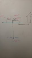
Environment: Well depth = 190 ft, no pit-less adapter (comes straight out the top of the well cap)
Attached is a picture of my setup. I have take some steps to trouble shoot this and would like to get others thoughts if you agree before committing to pull the well.
Recently pump motor will only push 35 PSI and will not shut off, even if I lower the set point on the constant pressure motor controller. If I turn off the pump motor, the pressure decreases to 0 in about 30 seconds. If I close the shutoff valve which isolates the lines from the well house to the house, and I turn the pump motor off, the pressure decreases to 0 in about 3 seconds. This tells me it is not a leak between the well and the house, and has to be somewhere in the well.
Below is a list of potential causes and my conclusion.
Cause 1 - Leak between the well and the house.
Answer - No. Pressure still decreases to 0 when I isolate that section at the shutoff valve.
Cause 2 - Bad pressure switch making it so the motor does not turn off.
Answer - No. If it was a bad pressure switch and motor kept on pumping as normal, the pressure would be able to reach 50 or more.
Cause 3 - Bad check/bypass valves in the line between motor and well head.
Answer - No. This would explain why pressure decreases to 0 when the motor is turned off, but does not explain why pressure will not build up higher than 35 psi.
Cause 4 - Leaking pump seals so pressure will not build
Answer - No. This would explain why the pressure will not build above 35 psi, but does not explain why pressure falls to 0 almost instantly once it is turned off. The check valves would keep the pressure built up.
Cause 5 - Hole/leak in the line between pump and pressure gauge switch.
Answer - Yes. This would explain why the pressure will not build up beyond 35 psi, and why the pressure decreases to swiftly when motor is not on. This also explains why the motor is constantly running. for example, if the motor controller set point is reduced to 20 psi, the pump reaches 20, but as soon as it starts to back off, the pressure drops with it so it just keeps running to keep the pressure at the set point.
What do you all think? Am I missing anything?
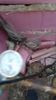
Question 2 - Since I do not have a pit-less adapter, and my water lines comes out the top of the well cap, how can I remove the well cap to see what type of water line is connecting the well cap and the pump? I just want to be sure that the water line doesn't drop into the well if I unbolt the cap. I want to look inside and confirm it is flexible piping and not rigid metal piping. Once I confirm this, it will help in my decision as to weather or not I hire to have the well pulled, or have myself and two helpers do this repair.
Thanks for the tips!
Problem: Decreased pressure from well. Only pushing 35 psi. Usually pushing 55 psi.
Proposed Cause: Leak in the line between the Pump and the pressure gauge.
Environment: Well depth = 190 ft, no pit-less adapter (comes straight out the top of the well cap)
Attached is a picture of my setup. I have take some steps to trouble shoot this and would like to get others thoughts if you agree before committing to pull the well.
Recently pump motor will only push 35 PSI and will not shut off, even if I lower the set point on the constant pressure motor controller. If I turn off the pump motor, the pressure decreases to 0 in about 30 seconds. If I close the shutoff valve which isolates the lines from the well house to the house, and I turn the pump motor off, the pressure decreases to 0 in about 3 seconds. This tells me it is not a leak between the well and the house, and has to be somewhere in the well.
Below is a list of potential causes and my conclusion.
Cause 1 - Leak between the well and the house.
Answer - No. Pressure still decreases to 0 when I isolate that section at the shutoff valve.
Cause 2 - Bad pressure switch making it so the motor does not turn off.
Answer - No. If it was a bad pressure switch and motor kept on pumping as normal, the pressure would be able to reach 50 or more.
Cause 3 - Bad check/bypass valves in the line between motor and well head.
Answer - No. This would explain why pressure decreases to 0 when the motor is turned off, but does not explain why pressure will not build up higher than 35 psi.
Cause 4 - Leaking pump seals so pressure will not build
Answer - No. This would explain why the pressure will not build above 35 psi, but does not explain why pressure falls to 0 almost instantly once it is turned off. The check valves would keep the pressure built up.
Cause 5 - Hole/leak in the line between pump and pressure gauge switch.
Answer - Yes. This would explain why the pressure will not build up beyond 35 psi, and why the pressure decreases to swiftly when motor is not on. This also explains why the motor is constantly running. for example, if the motor controller set point is reduced to 20 psi, the pump reaches 20, but as soon as it starts to back off, the pressure drops with it so it just keeps running to keep the pressure at the set point.
What do you all think? Am I missing anything?
Question 2 - Since I do not have a pit-less adapter, and my water lines comes out the top of the well cap, how can I remove the well cap to see what type of water line is connecting the well cap and the pump? I just want to be sure that the water line doesn't drop into the well if I unbolt the cap. I want to look inside and confirm it is flexible piping and not rigid metal piping. Once I confirm this, it will help in my decision as to weather or not I hire to have the well pulled, or have myself and two helpers do this repair.
Thanks for the tips!