Hello! This is my first post on this forum but have been using it as a resource for various projects. I am hoping to get a little advice on my DWV rework for a bathroom remodel. I plan to get this work inspected so pointers would be much appreciated. Please see the attached proposed plans along with pictures of current state.
Background
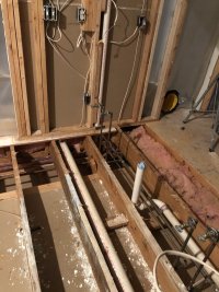
I am remodeling a home built in 96. I was hoping to swap the shower and vanity locations (both 2") and just move the tub a few feet. After opening everything up, I think I am seeing some code violations already. I am hoping to salvage as much as I can from what is already in place. Specifically I am hoping to put as few new holes in the joists as possible.
Local Code
This remodel is taking place in Forsyth County GA. County should be following IPC with a few GA state specific amendments. I don't think these amendments will be related to this project.
Questions
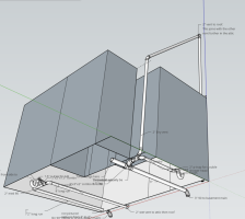
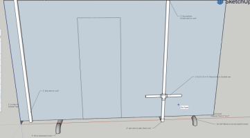
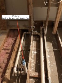
1. Am I correct in thinking that the horizontal dry vent below the flood level rim pictured in bath-lav01/02 is an IPC code violation? I am not sure how this passed inspection originally.
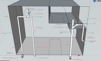
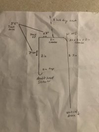
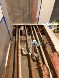
2. I would like to get feedback on my current plans (bath-lav-prop and shower-wc-prop). Do you think they would pass inspection (assuming the install was proper)?
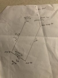
3. Would the wet vent length pictured in bath-lav-prop be acceptable? I am unclear whether the total slope for a wet vent can exceed the pipe size similar to a trap arms. I am under the impression the only requirement is to maintain 1/4 per foot slope regardless of length. Seems like you could run into the same trouble as with excessive trap arm length though. I can make new holes and shorten this run if need be. I have plenty of leeway on the tub trap arm length.
4. Should/can I switch to a 1.5 inch dry section of vent in shower-wc-prop? I am pretty sure this should meet code but I wasn't sure if it would be a good idea for a double head shower. 1.5 would be easier to put in the wall but I don't want to undersize.
5. If all seems well (unlikely), are there any reasonable recommendations to improve the system? I want to pass the IPC inspection but I also would like this to be a good long term solution.
(edit) I forgot to mark that the double lav would be a 2 x 2 x 1.5 x 1.5 fixture tee if I can get it or a double sani.
Background
I am remodeling a home built in 96. I was hoping to swap the shower and vanity locations (both 2") and just move the tub a few feet. After opening everything up, I think I am seeing some code violations already. I am hoping to salvage as much as I can from what is already in place. Specifically I am hoping to put as few new holes in the joists as possible.
Local Code
This remodel is taking place in Forsyth County GA. County should be following IPC with a few GA state specific amendments. I don't think these amendments will be related to this project.
Questions
1. Am I correct in thinking that the horizontal dry vent below the flood level rim pictured in bath-lav01/02 is an IPC code violation? I am not sure how this passed inspection originally.
2. I would like to get feedback on my current plans (bath-lav-prop and shower-wc-prop). Do you think they would pass inspection (assuming the install was proper)?
3. Would the wet vent length pictured in bath-lav-prop be acceptable? I am unclear whether the total slope for a wet vent can exceed the pipe size similar to a trap arms. I am under the impression the only requirement is to maintain 1/4 per foot slope regardless of length. Seems like you could run into the same trouble as with excessive trap arm length though. I can make new holes and shorten this run if need be. I have plenty of leeway on the tub trap arm length.
4. Should/can I switch to a 1.5 inch dry section of vent in shower-wc-prop? I am pretty sure this should meet code but I wasn't sure if it would be a good idea for a double head shower. 1.5 would be easier to put in the wall but I don't want to undersize.
5. If all seems well (unlikely), are there any reasonable recommendations to improve the system? I want to pass the IPC inspection but I also would like this to be a good long term solution.
(edit) I forgot to mark that the double lav would be a 2 x 2 x 1.5 x 1.5 fixture tee if I can get it or a double sani.
Attachments

Last edited: