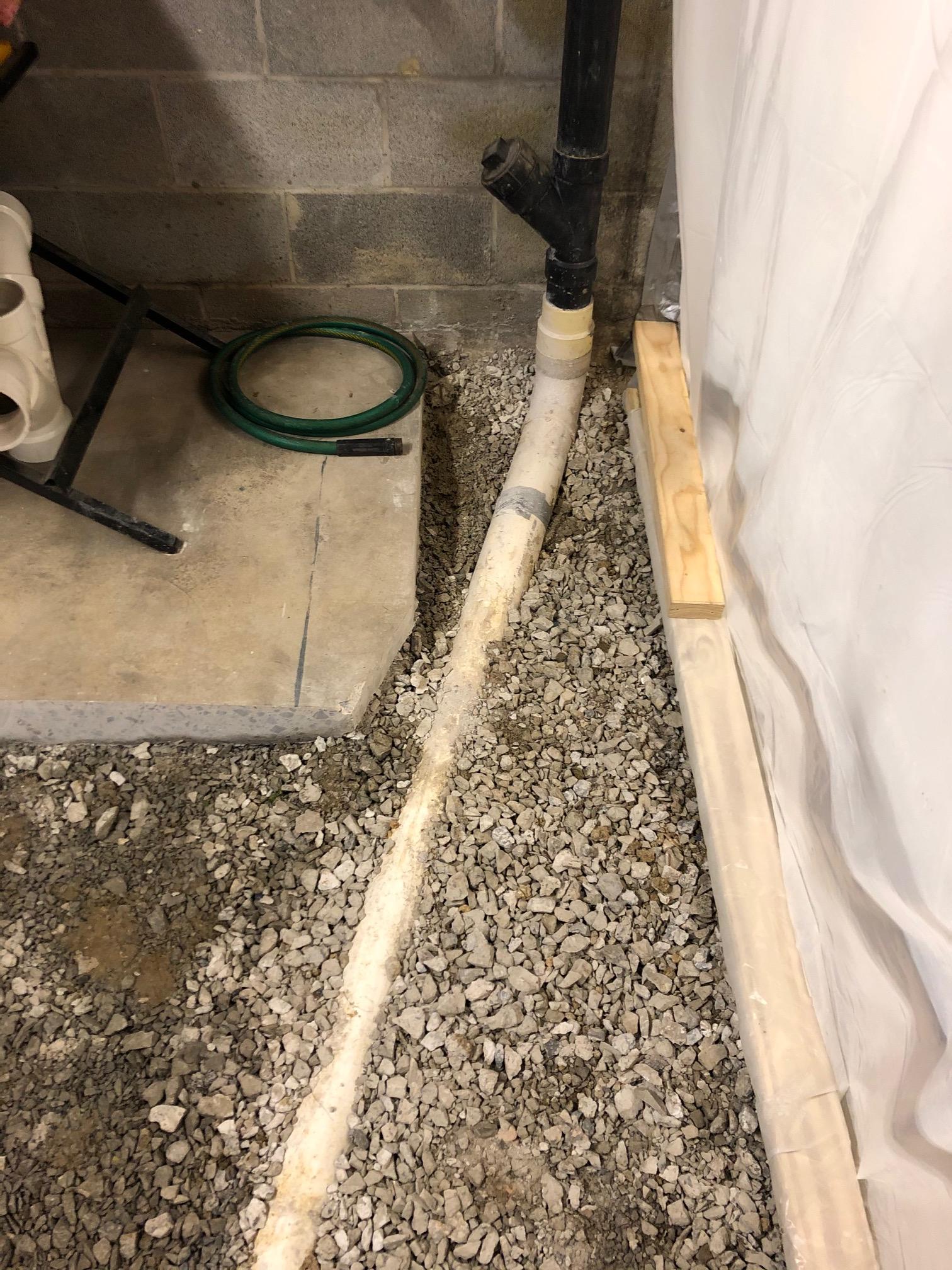
Presumably the vertical run is in the 2x8 wall or right next to it. Is that vertical run just one joist bay over from the current double wye?
The wall is the very next joist bay.
Are you looking to do the minimum rework necessary to get the double wye in for the toilet without making the headroom worse, or are you happy to redo all the drains below the floor to get more headroom? For example, I think you could wet vent both toilets and the shower via the lavatory, using a double wye on the horizontal rather than on the vertical.
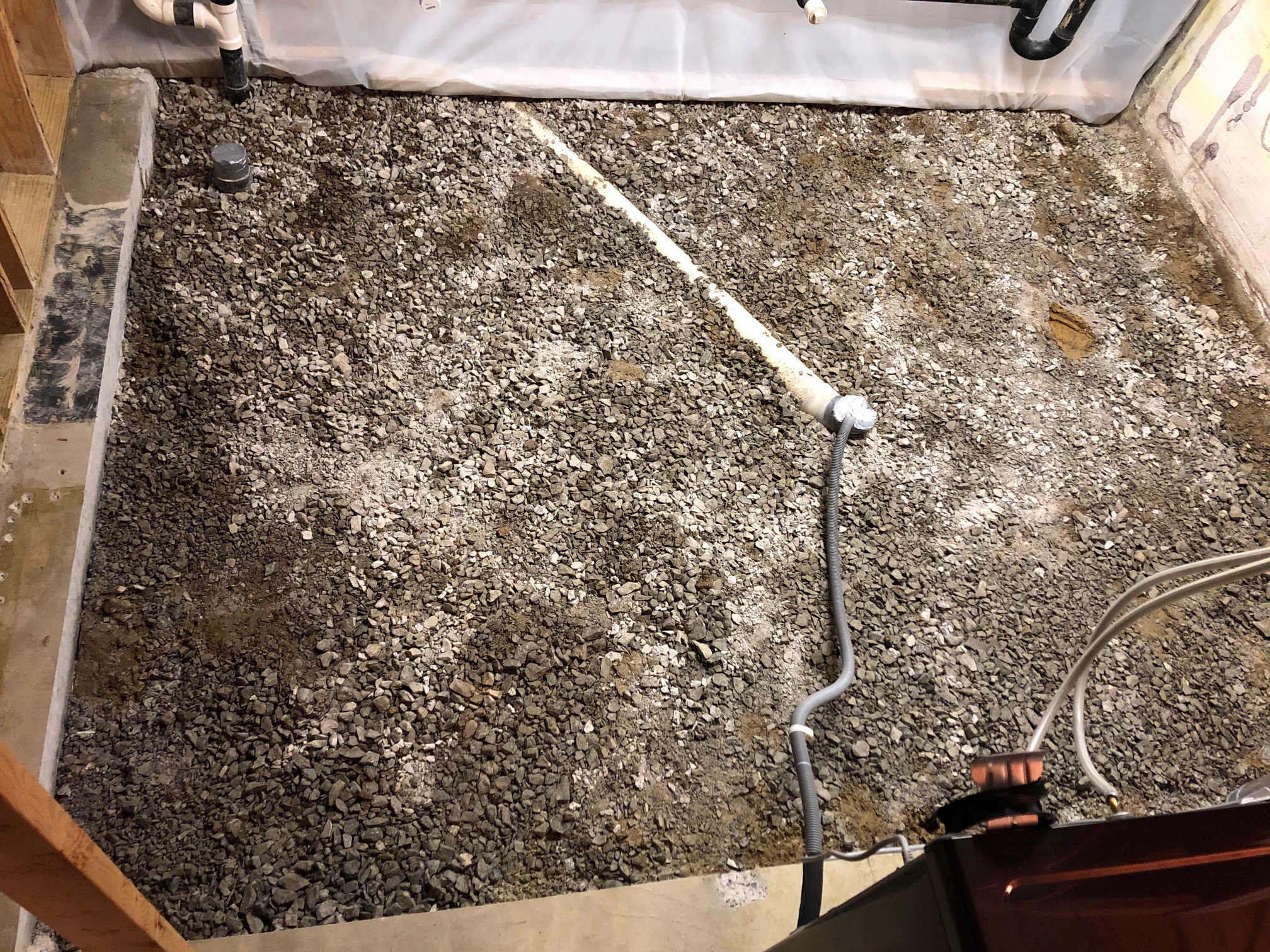
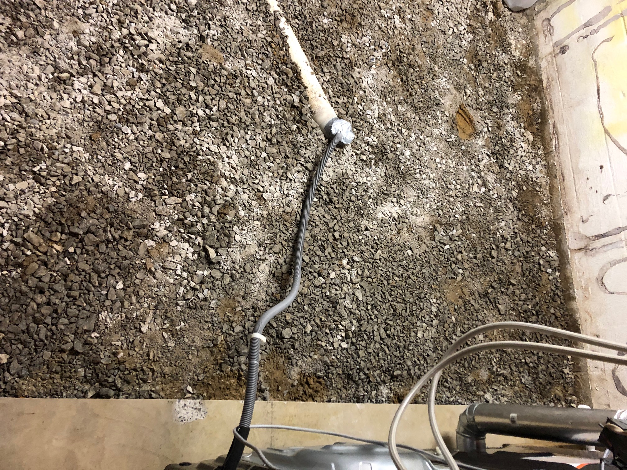
Everything under slab is rearranged already, so making changes is fine. I do not want to make headroom worse.
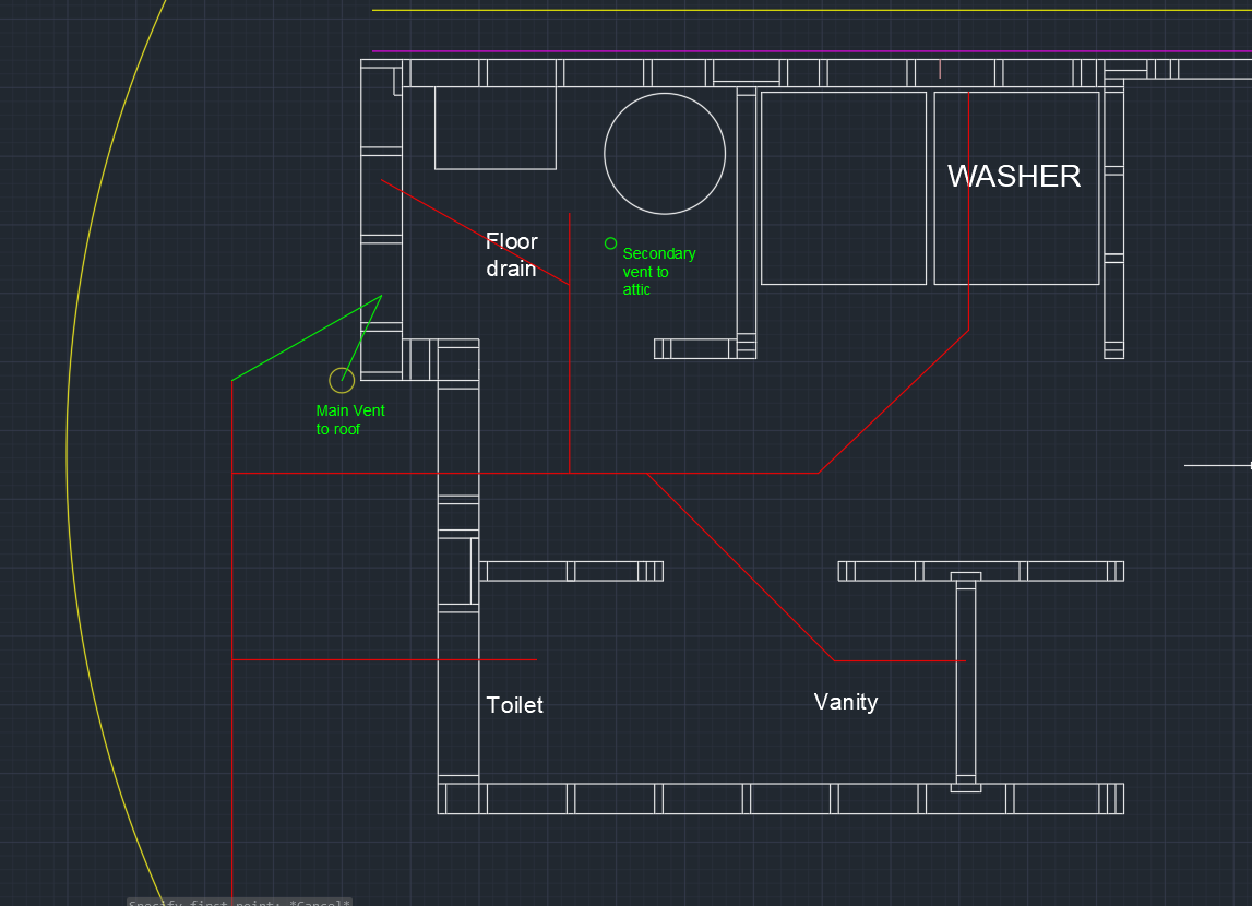
And BTW, I see two toilets a shower and a lavatory, is there not a second lavatory associated with the second toilet? Or is it just drained separately?
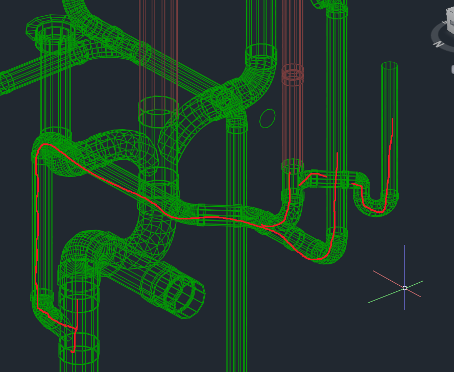
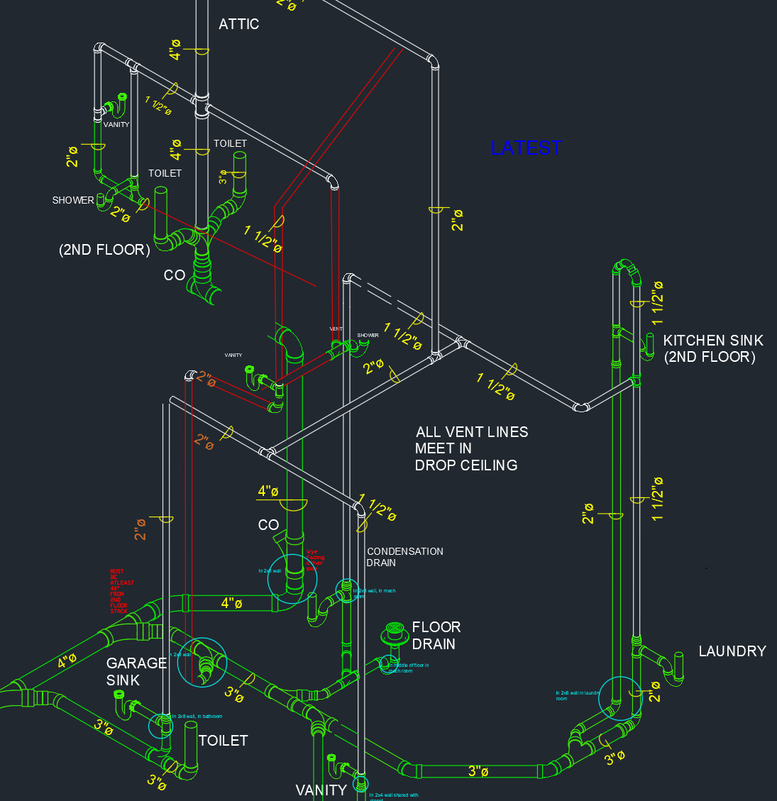
Yes, it is on the other side, I already completely rearranged it. Here is an earlier drawing with labels:
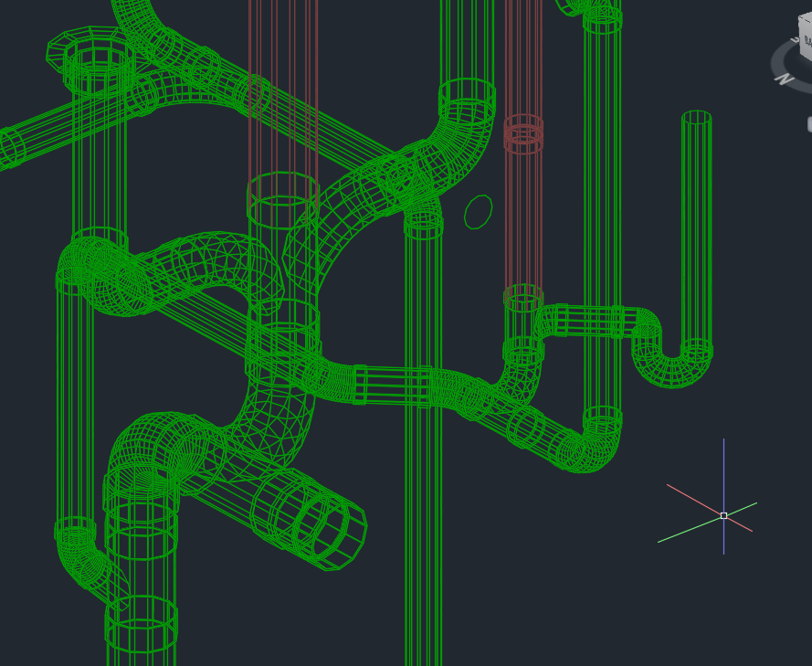
OK, there's about a zillion possible placements and orientations of a double wye to get everything connected. Here's one option that I'm currently thinking is good. If it seems viable I can try to draw it up for you if it would help:
Yeah, just some basic lines over my current drawing would be great.
 90% just kidding.