43v in circuit when breaker switched off

Users who are viewing this thread

SDmark

Member
Messages
67
Reaction score
1
Points
8
Location
San Diego, Calif.
Interesting article on ghost (stray) voltage: en.wikipedia.org/wiki/Stray_voltage. The last section discusses the use of a resistor shunt as you (or was it DonL) suggested. I see that Fluke even makes special stray voltage adapter (3 K ohm) and dual-impedence voltmeters.

I don't doubt that you and others here bring tremendous knowledge of electricity, in some cases probably exceeding what an electrician would know. On the other hand, an (experienced) residential electrician might be able to say, "yeah that stray voltage is normal on an 80-foot run, just ignore it," or "in 90% of cases, that's a grounding issue," or "the stray voltage is worrisome but first get that Stab Lok subpanel out of your house before you blow up."

It seems like you're a trouble shooter for data or telephony
I'm an IT guy and programmer, yes with an analytical streak. I've done my own phone, network, and electrical wiring for decades, including 18 years in this house. I also do plumbing, drywall, and painting under duress ;).
 

Bluebinky

Member
Messages
588
Reaction score
16
Points
18
Location
Des Moines, WA
I'm not an electrician. But as a former technician and electrical engineer, I agree with everyone else. Measuring voltages with a DMM on open wires run near other energized wires will drive you nuts. Use an analog meter, an old-style neon bulb tester, or provide a some kind of load with the DMM -- a 100k 1/4W resistor will work for energized 120V (but not 240V) without burning out.
 

SDmark

Member
Messages
67
Reaction score
1
Points
8
Location
San Diego, Calif.
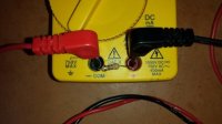
Folks here have been recommending a 10K to 100K resistor shunt for the multimeter to reduce impedance and "kill" ghost voltage, but I saw that Fluke's $70 SV225 shunt is only 3K. So I decided to start small and bought 3.3K 1/2 watt resistors at Radio Shack (5 for $1.49). With one of those bridging the multimeter's leads and measuring at the first junction box after the panel:

Only # 3 On
B+W 116.3 mV
R+W 120.0 V
B+R 243.5 mV

Only #13 On
B+W 119.0 V
R+W 143.0 mV
B+R 191.4 mV

Both #3 and #13 On
B+W 118.8 V
R+W 120.6 V
Got a burning smell on B+W,maybe from holding probes on 120V too long, so did not measure what should be 240V on B+R.

My 43v mystery voltage has gone down to 116 - 143 mV. Good, right?

Multimeter resistor.jpg
 

Reach4

Well-Known Member
Messages
38,892
Reaction score
4,435
Points
113
Location
IL
120 V across 3300 ohms is 4.36 watts. You have a 1/2 watt resistor. So keep any measurements across 120 volts very brief.

Good useful test. Yes there is a problem with your wiring.

243.5 mV across 3.3K is 73.9 milliamps.

Could you post numbers with both breakers off? The reason for that is to confirm that the problem is with only the 3 wires that you are considering.
 
Last edited:

Widgit Maker

Member
Messages
173
Reaction score
21
Points
18
Location
Alexandria, Virginia
Earler You said.

Breakers off
B+W panel 7.5v, jbox 7.5v
R+W panel 7.3v, jbox 7.4v
B+R panel 109mv, jbox 130mv

Only#3 On
B+W panel 39v, jbox 38v
R+W panel 119.5v, jbox 119.7v
B+R panel 76v, jbox 76.4v

Only#13 On
B+W panel 117.5v, jbox 117.0v
R+W panel 46.4v, jbox 46.6v
B+R panel 66.0v, jbox 66.0v

Both #3 and #13 On
B+W panel 117.1v, jbox 117.2v
R+W panel 120.1v, jbox 120.1v
B+R panel 238.5v, jbox 238.5v

I think you have another circuit back feeding one of these circuits or the neutral of this cable.
Something on the circuit that is back feeding has been turned off. That's why your 43v went away.

Suggest that you turn other circuits off, one at a time and check your readings for a change, When you find a change, turn the back feeding circuit back on and then start turning things on that circuit on and off or disconnecting. It is likely that the back feeding connection is a heating appliance.
 

Reach4

Well-Known Member
Messages
38,892
Reaction score
4,435
Points
113
Location
IL
Breakers off
B+W panel 7.5v, jbox 7.5v
R+W panel 7.3v, jbox 7.4v
B+R panel 109mv, jbox 130mv

At this point, let's make sure you did not destroy the resistor when you let the smoke out. (that phrase "let the smoke out" is an old joke.) Switch to a different resistor, OR put the meter in ohms (with the leads not touching anything) and read the resistance. If the meter does not say less than 3.7 K, discard that resistor. If it says about 3.3K, you can continue using that resistor after switching back to AC volts.

If you get those voltages and the resistor is good, there would be something leaking to the wires that you have been measuring. Start turning off other breakers until the voltages, with breakers #3 and #13 still off, drop much lower.
 

SDmark

Member
Messages
67
Reaction score
1
Points
8
Location
San Diego, Calif.
Could you post numbers with both breakers off?
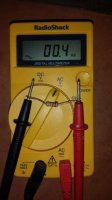
I used a new resistor. Had more trouble this time getting the temporary leads to stay in the multitester with the resistor, so this time I wrapped the resistor around the tips of the leads and re-ran all tests.
Multimeter with resistor 2.jpg

Both circuits Off
B+W 21.1 mV
R+W 21.0 mV
B+R 0.4 mV
Multitester with resistor but not touching any wires: 0.4 mV

Only # 3 On
B+W 124.6 mV
R+W 120.0 V
B+R 6.5 mV

Only #13 On
B+W 119.5 V
R+W 154.5 mV
B+R 20.6 mV

Both #3 and #13 On
B+W 119.1 V
R+W 119.2 V
B+R skipped due to expected 240
Something on the circuit that is back feeding has been turned off. That's why your 43v went away.
The 43V went away only when I bridged the multimeter leads with a resistor, lowering its impedance. As soon as I removed the resistor, the 43V was visible again. I already did a test where I turned off all other circuits in the house, but still had the 43V (see post #50).
 

Reach4

Well-Known Member
Messages
38,892
Reaction score
4,435
Points
113
Location
IL
OK. Useful testing.

154.5 mV across 3.3 kohm is 47 ma. (whoops) 5 ma is would blow a GFCI.

I suspect the leakage gets bigger when it rains.

You should fix your wiring.
 
Last edited:

DonL

Jack of all trades Master of one
Messages
5,205
Reaction score
72
Points
48
Location
Houston, TX
Your meter is not reading correct if you are reading voltage from a resistor connected to nothing but the meter leads. :eek:

28526-c65be207429e6da9318d36d9966e0e5b.jpg


I think you should read the resistance from Ground to Neural.

The Resistance should be near Zero, And should be tested with power off.

Good Luck.
 

SDmark

Member
Messages
67
Reaction score
1
Points
8
Location
San Diego, Calif.
Your meter is not reading correct if you are reading voltage from a resistor connected to nothing but the meter leads.
Yeah the meter may be buggy especially at millivoltages. With no resistor, it's jumping around from 10 mV to 300 mV or more, only briefly settling on 0.0L. It's like the auto-ranging is constantly trying to figure out how to read. The resistor stabilizes it at 0.4 mV.
I think you should read the resistance from Ground to Neural. The Resistance should be near Zero
Doesn't that assume that there is ground wire that eventually goes back to the main panel?

The main does have a separate ground buss.

The subpanel does not have a ground buss bar. There is no ground wire from the subpanel to the main panel, although that might be metallic conduit. All the cables exiting the subpanel are NM.

This particular junction box has no ground wire.

A nearby outlet is grounded, but I suspect (hope) that ground comes from a clamp on a local copper water pipe since it's not coming from the subpanel.

If I measure from neutral in the junction box to ground in a nearby outlet, there is no continuity.

Meanwhile, I just pulled a permit to replace the subpanel. We'll see if that makes a difference.
 

DonL

Jack of all trades Master of one
Messages
5,205
Reaction score
72
Points
48
Location
Houston, TX
Yeah the meter may be buggy especially at millivoltages. With no resistor, it's jumping around from 10 mV to 300 mV or more, only briefly settling on 0.0L. It's like the auto-ranging is constantly trying to figure out how to read. The resistor stabilizes it at 0.4 mV.

Doesn't that assume that there is ground wire that eventually goes back to the main panel?

The main does have a separate ground buss.

The subpanel does not have a ground buss bar. There is no ground wire from the subpanel to the main panel, although that might be metallic conduit. All the cables exiting the subpanel are NM.

This particular junction box has no ground wire.

A nearby outlet is grounded, but I suspect (hope) that ground comes from a clamp on a local copper water pipe since it's not coming from the subpanel.

If I measure from neutral in the junction box to ground in a nearby outlet, there is no continuity.

Meanwhile, I just pulled a permit to replace the subpanel. We'll see if that makes a difference.


Do not assume. Measure it to make sure your Neutral makes it back to ground in the main panel.

You need a new meter or it needs a new battery. It should read 0 when not connected. Does it read 0 with the probes removed ?

Good Luck.
 

SDmark

Member
Messages
67
Reaction score
1
Points
8
Location
San Diego, Calif.
Do not assume.
I was asking whether you are assuming I have a ground wire. I don't. Maybe I can jerry-rig an extension cord to wrap around the house and test directly to ground at the main panel.

On the meter, there is no change with new batteries or unplugging the probes.
 

DonL

Jack of all trades Master of one
Messages
5,205
Reaction score
72
Points
48
Location
Houston, TX
On the meter, there is no change with new batteries or unplugging the probes.

Are your outlets 3 prong ? If so, one may be wired wrong and neutral is connected to ground at the outlet.

You need a new meter. You are chasing your tail.

Walmart sells cheap meters. Get one that reads 0 with nothing connected to it.
 
Last edited:

SDmark

Member
Messages
67
Reaction score
1
Points
8
Location
San Diego, Calif.
Some outlets are three-prong but as best I can tell, they are "locally" grounded--the ground wire does not feed back to the main panel.

I just ordered a Fluke 117 which has a built-in "Low-Z" function. Hopefully that will take one variable (untrustworthy meter) out of the equation.
 

Jadnashua

Retired Defense Industry Engineer xxx
Messages
32,770
Reaction score
1,190
Points
113
Location
New England
Neutral coming into the house is a current carrying conductor. If it is not located perfectly half-way between L1 and L2 on the transformer, there can be some difference between measuring L1-N and L2-N. Then, for the neutral to be 'safe', we tie it to ground in the house. In today's code, you MUST run a 4-wire cable from the main panel to the subpanel: L1, L2, N, ground, and the ground must not be tied to the neutral in the subpanel.

Older panels could have some corrosion on them and allow some current to flow. With long-term use, there could be some metal particles in the CB. Replacing the CB's, or putting in a new subpanel feed with the proper ground may solve the problem. Have you tried popping out any of the CBs and looking at their contacts and the bus bar?

In today's houses that could have repairs or full use of plastic piping, sometimes the supply line coming into it as well, the use of a copper water pipe as a ground point is unsafe, unreliable, and should not be done. Bonding a good ground point to the pipes, though, is still a good idea.

If you want 3-wire (grounded) receptacles and do not have a ground wire present, install either a GFCI CB, or one in-line, then use the load side to feed others down-stream. You must mark them as GFCI protected, no ground, and many of the devices come with labels for this purpose in the box.

If you have any 240vac (double) breakers in the panel, you could try popping them out and remeasure. X10 devices may have required a bridge between phases to make things work across legs, and those could be a problem. If you have any 240vac appliances, and they have plugs, unplug them.
 

DonL

Jack of all trades Master of one
Messages
5,205
Reaction score
72
Points
48
Location
Houston, TX
Some outlets are three-prong but as best I can tell, they are "locally" grounded--the ground wire does not feed back to the main panel.

I just ordered a Fluke 117 which has a built-in "Low-Z" function. Hopefully that will take one variable (untrustworthy meter) out of the equation.

If any of those "locally" grounded outlet are connected to Neutral at the outlet you can have problems.

That meter is a good one. Enjoy your new toy.
 

SDmark

Member
Messages
67
Reaction score
1
Points
8
Location
San Diego, Calif.
plastic piping
That's one issue I don't have in this 1953 house. All supply pipe is copper. However, at some point after Cox buried a grounding rod, the main panel is now grounded to the grounding rod, with water main tied to that. And I was wrong what I said a few pages ago about grounding rod for the pool subpanel I installed. I did in fact install one by the subpanel, but there is nothing connected to it--the subpanel's ground wire goes only to the main panel. (So the inspector didn't make me add the ground rod, he made me ignore the new ground rod I thought I needed and connect ground to the main panel.)
If you want 3-wire (grounded) receptacles and do not have a ground wire present, install either a GFCI CB
Interesting suggestion...will be an easier option after I replace the subpanel.
If any of those "locally" grounded outlet are connected to Neutral at the outlet you can have problems.
Haven't seen that yet. What I have seen is a ground wire coming in the the back of a junction box. Maybe I could us my tone generator and probe to get a better idea where that comes from.

So in these old outlets that don't or can't tie back to the separate ground in the panel, which is preferable?

1) Use a GFCI breaker.
2) Use a separate ground wire tied to ground near the outlets.
3) Both.
 

Jadnashua

Retired Defense Industry Engineer xxx
Messages
32,770
Reaction score
1,190
Points
113
Location
New England
FWIW, in most new construction, in most locations, if they are using the latest code cycle, GFCI and AFCI protection is required on almost every receptacle installed in a dwelling! ANd, a newer requirement is that you must have a neutral at the switch location, and not just a switch leg.

An actual ground is still a very useful inclusion in the plan, but keep in mind what it is for: primarily, to provide an alternate patch back to the panel to trip the protection device (fuse or CB). Some things, like surge suppressors are only fully effective with a real ground. A GFCI protects an individual from power that may leak from a defective device. An AFCI protects the dwelling from a fire if there is a loose or corroded connection that may arc and catch something on fire. The CB or fuse protects the wiring from overheating and melting. They all are important.

Without rewiring the entire house, a GFCI is a useful addition. The ground should run back to the power line coming into the house. Random alternate grounding points may or may not be effective, as that will depend a huge amount on the soil type, its moisture content, and the state of the grounding device. Keep in mind that the goal is to be able to trip the safety device, and that will only occur if the ground point is intimately connected to the ground point at the power entry where neutral and ground are tied together. Trying to ground things elsewhere does NOT provide the same effect. Bonding, on the other hand, is a similar issue, but somewhat separate from grounding. You would bond your water pipes, but not generally use them as a ground point. Power needs a complete, low resistance path to enable the protection devices, and an arbitrary ground often will NOT provide that.
 

SDmark

Member
Messages
67
Reaction score
1
Points
8
Location
San Diego, Calif.
The Fluke 117 is here.

With the Fluke set to "Auto-V LoZ" (with 3K ohm anti-ghost resistor):

Both circuits Off
B+W 0.0 V
R+W 0.0 V
B+R 0.0 V
Multitester not touching any wires: 0.0 mV

Only # 3 On
B+W 0.1 V
R+W 119.5 V
B+R 0.3 V

Only #13 On
B+W 120.1 V
R+W 0.2 V
B+R 0.2 V

Both #3 and #13 On
B+W 120.1 V
R+W 119.7 V
B+R 239.9 V

Note that the Fluke does not show mV in this mode but 0.1 to 0.2 V = 100 mV to 200 mV, which is in line with yesterday's tests with the Radio Shack meter and the resistor.

With the Fluke set to AC Volts (no anti-ghost resistor):

Both circuits Off
B+W 7.19 V
R+W 0.037 V
B+R 0.558 V
Multitester not touching any wires: 0.0 V (but as high as 0.130 V when near my laptop)

Only # 3 On
B+W 36.69 V
R+W 119.3 V
B+R 72.4 V

Only #13 On
B+W 121.0 V
R+W 45.85 V
B+R 64.93 V

Both #3 and #13 On
B+W 120.2 V
R+W 119.9 V
B+R 240.0 V

So yeah, the Fluke can see the ghost voltage when it's not compensating for it.
154.5 mV across 3.3 kohm is 47 ma.
If this calculator is correct, it's 47 micro-amps or 0.047 mA. To get up to 5 mA, I'd have to have 16.5 V across 3300 ohms (yesterday's resistor) or 15 V across 3000 ohms (Fluke's resistor). So about 75-100 times more amps than the "dead" circuit is carrying. Am I checking that correctly?
 
Last edited by a moderator:

Reach4

Well-Known Member
Messages
38,892
Reaction score
4,435
Points
113
Location
IL
If this calculator is correct, it's 47 micro-amps or 0.047 mA. To get up to 5 mA, I'd have to have 16.5 V across 3300 ohms (yesterday's resistor) or 15 V across 3000 ohms (Fluke's resistor). So about 75-100 times more amps than the "dead" circuit is carrying. Am I checking that correctly?
You are correct, and I was wrong.
 
Top
Hey, wait a minute.

This is awkward, but...

It looks like you're using an ad blocker. We get it, but (1) terrylove.com can't live without ads, and (2) ad blockers can cause issues with videos and comments. If you'd like to support the site, please allow ads.

If any particular ad is your REASON for blocking ads, please let us know. We might be able to do something about it. Thanks.
I've Disabled AdBlock    No Thanks